
Illuminated bollard for loading dock

a loading dock and lighting technology, applied in the direction of lighting and heating equipment, lighting support devices, ways, etc., can solve the problems of collision damage and inability to address

Active Publication Date: 2012-03-20
JAMAS ENTERPRISES
View PDF13 Cites 6 Cited by
  • Summary
  • Abstract
  • Description
  • Claims
  • Application Information

AI Technical Summary

Benefits of technology

[0003]Accordingly, it is an object of the present invention to provide a dock light system that avoids the drawbacks of the prior art.
[0005]It is a more specific object to provide an illuminated bollard which is of simple construction, with clean lines and capable of providing good visibility into the interior of the truck or van being loaded or unloaded.
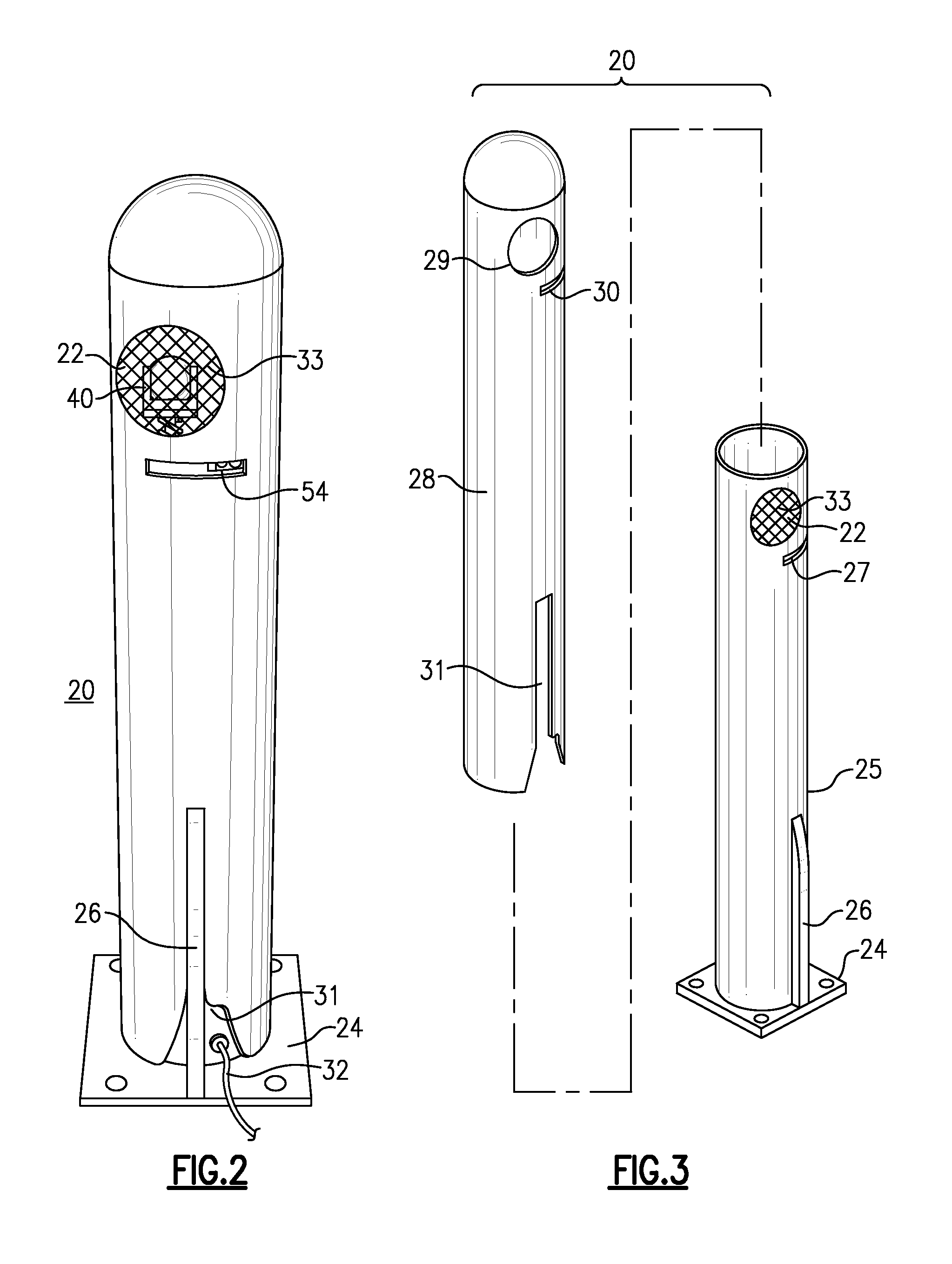
[0008]In a preferred mode, the illuminated bollard can have a plastic protective sleeve fitted over its tubular metal body, and the plastic sleeve has a window cutout therein aligned with the window cutout of the tubular metal body. Light from reflected from internal surfaces of the bollard illuminates the top of the sleeve, to increase visibility of the bollard.
[0010]The lens holder is supported on springs above the base plate, and these springs act to absorb some of the shock of collision with the fork lift or loading equipment and protect the lamp from damage.
[0012]A metal mesh screen is positioned in the bollard window cutout to protect the lamp assembly.

Problems solved by technology

These dock lights project out from the doorway or from the side of the bollard into the lanes that are traversed by the fork lifts or other equipment, and thus they are subject to collision damage.
The docking equipment industry is aware of this problem, but has been unable to address it.

Method used


Image

  • Illuminated bollard for loading dock
  • Illuminated bollard for loading dock
  • Illuminated bollard for loading dock

Examples


Embodiment Construction

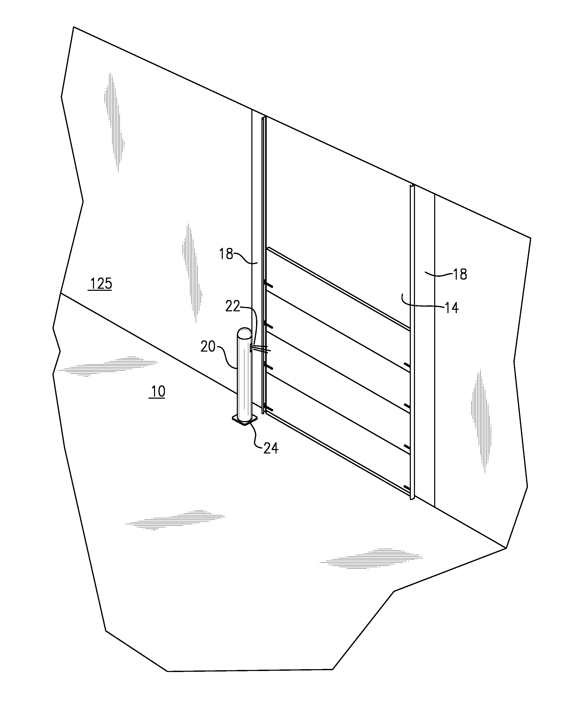
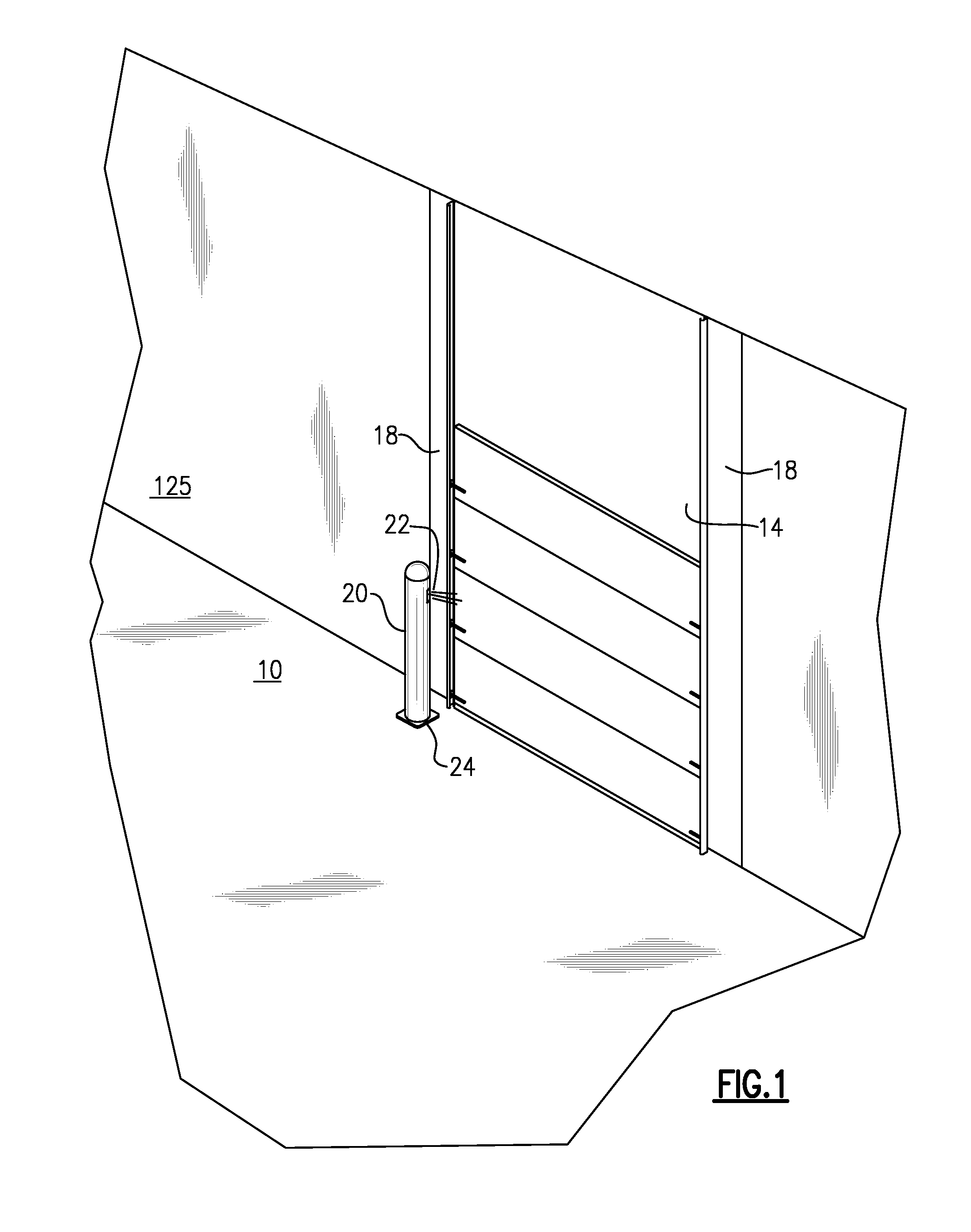
[0021]With reference now to the Drawing, FIG. 1 shows the interior of a loading dock area of a warehouse or other shipping or receiving area, with a floor 10, wall surface 12, and a dock door 14. The dock door slides up and down in vertical door guides 18 at its left and right sides. The dock door 14 is opened, by lifting it upwards, to access the interior of a truck body, van, or trailer that has been parked or spotted at the dock gate.

[0022]A bollard 20, i.e., a strong steel post, is affixed to the dock floor 10 just in front of the door guide 18 to protect the door and guide from accidental bumping by a fork lift or other loading equipment as it goes through the open dock door 14 into and out of the truck that is being loaded or unloaded. Typically, there is a bollard at each side of the loading dock gate, but only one is shown here for purposes of simplicity. One of the two bollards is illuminated, and the other is of the standard type. The bollards can be cylindrical or pipe bo...


PUM


Abstract

A combination dock light and bollard serves the purposes of both, without having any sensitive structure projecting out from the bollard into the traffic lane at the loading dock. A lamp assembly within the bollard projects out a window cutout at an upper end of the tubular metal body of the bollard. The lamp assembly rests on a sub-plate welded into the bollard below the cutout. The lamp holder is mounted on compression springs held in place with machine screw, to permit adjustment of the lamp beam direction. A photo eye turns the lamp on when the loading dock door is opened, and off when the dock door is closed.

Description

RELATED APPLICATIONS[0001]This application claims priority under 35 U.S.C. §119(e) of U.S. Provisional Pat. Application No. 61 / 091,742, filed Aug. 26, 2008, which is incorporated by reference herein.BACKGROUND OF THE INVENTION[0002]This invention relates to loading dock lighting systems, of the type intended to shine light inside a tractor trailer, van, railroad car, etc., when present at a loading dock at a warehouse or other shipping or receiving location. Loading vehicles, such as fork lifts and pallet lifters, are used in bringing goods and materials into a trailer or out of a trailer when the same is stationed at a loading dock. In order to help provide enough light for the fork lift operator during loading or unloading, it is often necessary to use a dock light. These items typically project from some structure, such as the edges or vertical guides of the dock door or gate, or can sometimes be installed on a post or bollard at the loading dock gate. One example of this is disc...

Claims


Application Information

Patent Timeline
Patent Type & Authority Patents(United States)
IPC IPC(8): F21V21/29F21S13/10
CPCE01F9/0165F21S8/083F21V23/0442H05B37/0209E01F9/617H05B47/10
Inventor HUDSON, DALE R.TILLMAN, JAY
Owner JAMAS ENTERPRISES
Learn More