Spinal interbody spacer

a technology of interbody spacer and spacer, which is applied in the field of spinal interbody spacer, can solve the problems of conventional prosthetic implants being dislodged or moved from the desired implantation location, and the normal occupied space between adjacent vertebrae being subject to collapse and/or misalignmen

Active Publication Date: 2012-03-20
K2M
View PDF28 Cites 215 Cited by
  • Summary
  • Abstract
  • Description
  • Claims
  • Application Information

AI Technical Summary

Problems solved by technology

After a partial or complete discectomy, the normally occupied space between adjacent vertebral bodies is subject to collapse and / or misalignment due to the absence of all or a part of the intervertebral disc.
However, there exists a possibility that conventional prosthetic implants may be dislodged or moved from their desired implantation location due to movement by the patient before sufficient bone growth has occurred.

Method used


Image

  • Spinal interbody spacer
  • Spinal interbody spacer
  • Spinal interbody spacer

Examples


Embodiment Construction

[0023]Embodiments of the presently disclosed spinal interbody spacer will now be described in detail with reference to the drawings, in which like reference numerals designate identical or corresponding elements in each of the several views.

[0024]In the drawings and in the description that follows, the term proximal refers to the portion of the device that is closest to the operator, while the term distal refers to the portion of the device that is furthest from the operator. Additionally, in the drawings and in the description that follows, terms such as front, rear, upper, lower, top, bottom, and the similar directional terms are used simply for convenience of description and are not intended to limit the disclosure attached hereto.

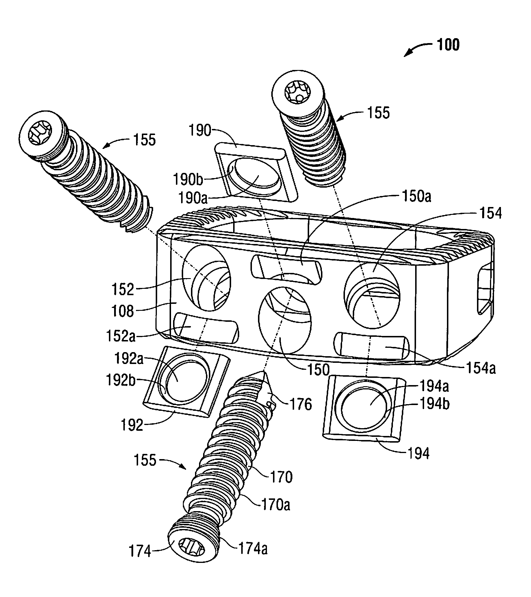
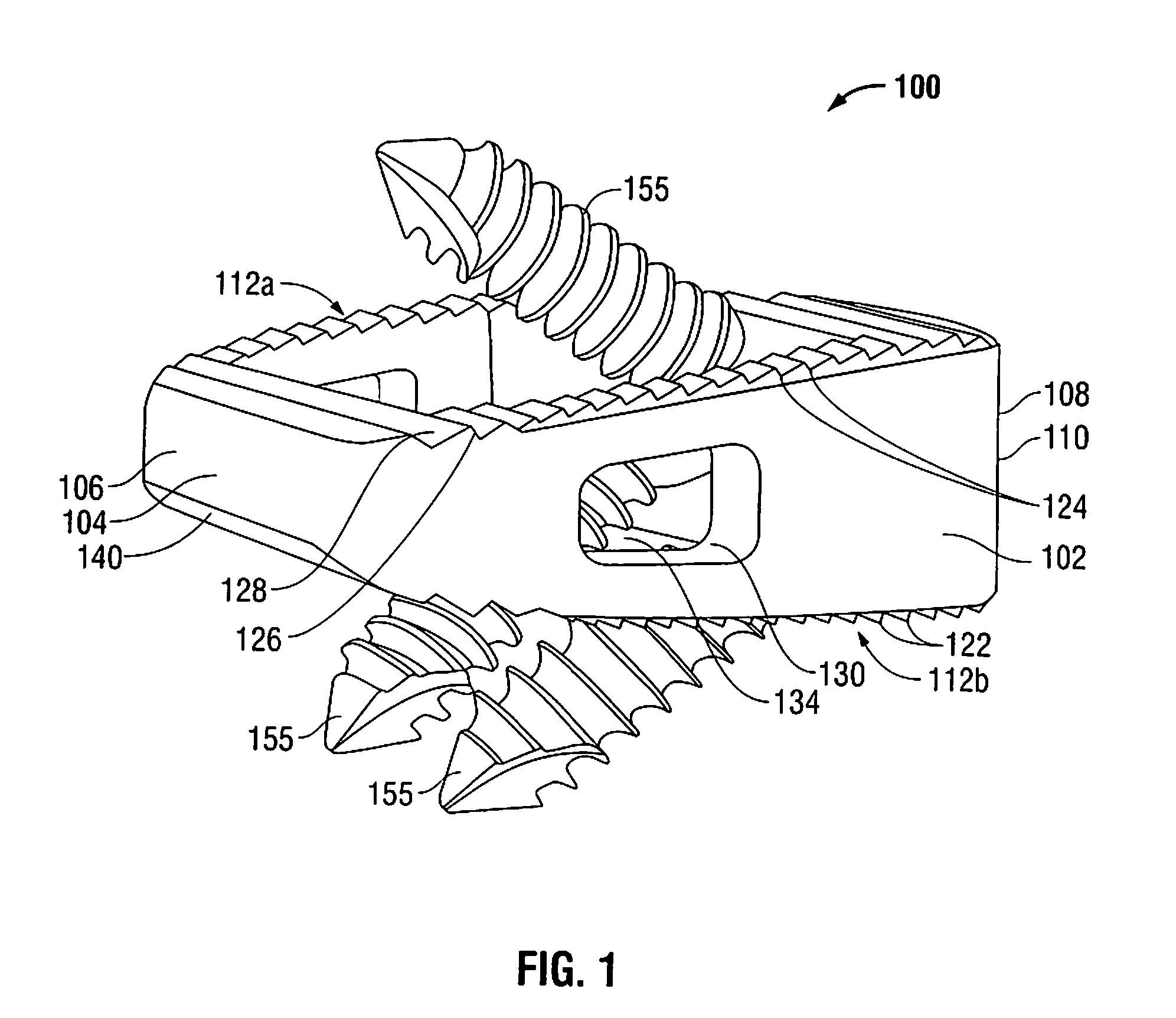
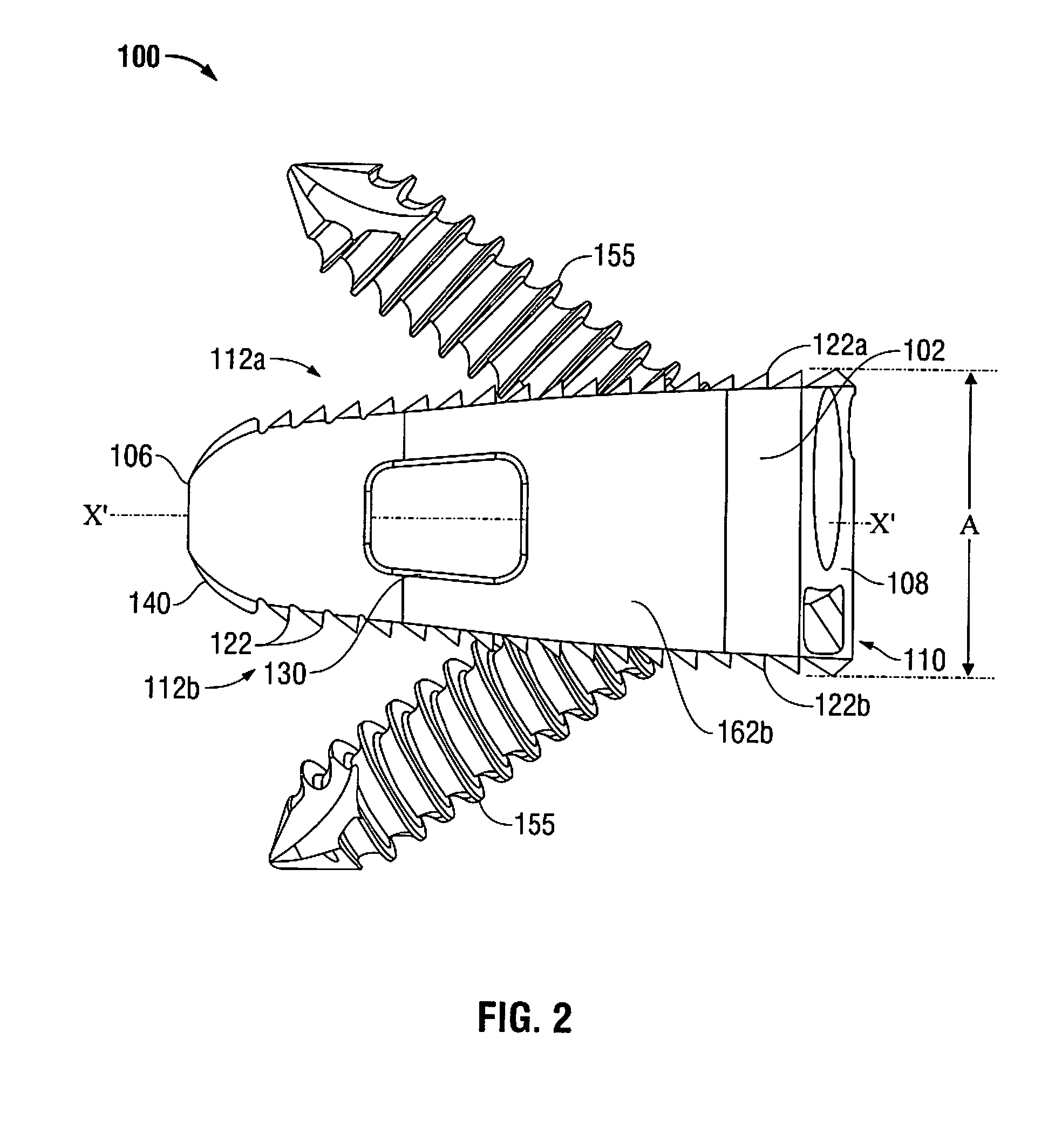
[0025]Referring now to FIGS. 1-5, there is disclosed an embodiment of a spinal interbody spacer 100 for engagement between vertebrae according to the present disclosure. More particularly, referring to FIGS. 1-3, spinal interbody spacer 100 includes a b...


PUM


Abstract

A spinal spacer for engagement between vertebrae includes a body extending between a substantially contoured first end surface and a second end surface to define side surfaces and opposing top and bottom vertebral engaging surfaces substantially symmetrical about a centerline axis. At least one opening defines a hollow inner body and includes first and second intersecting openings extending through the top and bottom vertebral engaging surfaces. The second intersecting opening extends through the side surfaces. The second end surface includes at least one aperture formed therethrough in communication with the hollow inner body. A screw opening is defined through at least one plate insert configured to be removably coupled to the second end surface to substantially align the screw opening with the at least one aperture. The bone screw is configured to be threadingly secured within the at least one plate insert.

Description

BACKGROUND[0001]1. Technical Field[0002]The present disclosure relates to devices for implantation between adjacent vertebrae. Specifically, the disclosure relates to a spinal interbody spacer that inhibits the collapse of the space between adjacent vertebrae after a discectomy.[0003]2. Background of Related Art[0004]After a partial or complete discectomy, the normally occupied space between adjacent vertebral bodies is subject to collapse and / or misalignment due to the absence of all or a part of the intervertebral disc. In such situations, the physician may insert one or more prosthetic spacers between the affected vertebrae to maintain normal disc spacing and / or the normal amount of lordosis in the affected region.[0005]Typically, a prosthetic implant is inserted between the adjacent vertebrae and may include pathways that permit bone growth between the adjacent vertebrae until they are fused together. However, there exists a possibility that conventional prosthetic implants may ...

Claims


Application Information

Patent Timeline
Patent Type & Authority Patents(United States)
IPC IPC(8): A61F2/44
CPCA61F2/447A61F2002/2817A61F2002/2835A61F2002/3008A61F2002/30517A61F2002/30774A61F2002/30787A61F2002/30904A61F2002/4475A61F2220/0025A61F2250/0098A61F2002/30593
Inventor KOSTUIK, JOHNMCCLINTOCK, LARRYWILLIAMS, JOHN I.
Owner K2M
Why Eureka
Try Eureka