Shoe sole with pivotal ground engaging plate

a technology of pivoting ground and shoe sole, which is applied in the field of shoe soles, can solve the problems of not being able to easily change and/or program the internal structure not being able to achieve the effect of facilitating the alteration of the pivoting characteristics of the shoe sole, facilitating the maintenance of the foot in a properly oriented position, and minimizing the movement of the foo

Inactive Publication Date: 2012-03-27
ALINE SYST INC
View PDF12 Cites 10 Cited by
  • Summary
  • Abstract
  • Description
  • Claims
  • Application Information

AI Technical Summary

Benefits of technology

[0004]Another object of the present invention is to provide a rigid foot support plate for supporting substantially the entire foot of the user and stabilizing the foot of a user during use of the shoe sole while pivotally attaching at least one other plate to a bottom surface of the foot support plate and allowing the bottom plate to pivot relative to the foot support plate and compensate for variations in the terrain, during use of the shoe sole, while still maintaining the foot in a relatively stable position.
[0005]A further object of the present invention is to minimize movement of the foot relative to the foot support plate, during use of the shoe sole, so that the foot remains in a substantially stable position at all times whereby the shoe sole correctly supports the heel, the arch and the ball of the feet of a user during use of the shoe sole.
[0006]Yet another object of the present invention is to provide one or more programming features or components, located between the top foot support plate and the bottom ground engaging plate, which facilitate altering the pivoting characteristics of the shoe sole so that the shoe sole is specifically adapted to respond, in a desired manner, or compensate for a desired motion during use of the shoe sole.
[0007]A still further object of the present invention is to provide a pivot, located between the foot support plate and the ground engaging plate, at a substantially fixed location which facilitates pivoting movement of the ground engaging plate relative to the foot engaging plate in at least one direction of movement, preferably two or more different directions of movement.
[0008]Still another object of the present invention is to eliminate substantially any to and fro sheering action of the bottom ground engaging plate relative to the top foot engaging plate as well substantially eliminate any Z-axis rotational movement of the ground engaging plate relative to the foot engaging plate while only substantially permitting pivoting movement of the ground engaging plate(s) relative to the foot engaging plate.
[0009]The present invention also relates to a shoe sole comprising: a rigid foot engaging plate for accommodating a foot of a user, during use of the shoe sole, so that the foot remains supported by the foot engaging plate during use of the shoe sole; at least one ground engaging plate supported by an undersurface of the foot engaging plate; and a pivot member being located between the foot engaging plate and the ground engaging plate to facilitate relative pivoting motion between the foot engaging plate and the ground engaging plate during use of the shoe sole The present invention also relates to a shoe sole comprising: a foot engaging plate for accommodating a foot of a user, the foot engaging plate being sufficiently rigid so as to resist distortion of the foot engaging plate, during use of the shoe sole, so that the foot remains supported by the foot engaging plate during use of the shoe sole; separate toe and heel ground engaging plates supported by an undersurface of the foot engaging plate in a spaced relationship from one another, the toe ground engaging plate having a pivot member located between the foot engaging plate and the toe ground engaging plate to facilitate relative pivoting motion between the toe ground engaging plate and the foot engaging plate, the heel ground engaging plate having a pivot member located between the foot engaging plate and the heel ground engaging plate to facilitate relative pivoting motion between the heel ground engaging plate and the foot engaging plate; and a layer of resilient material being sandwiched between the foot engaging plate and the toe ground engaging plate and a layer of resilient material being sandwiched between the foot engaging plate and the heel ground engaging plate.

Problems solved by technology

While a variety of shoe soles are known in the art, many of the current designs do not facilitate maintaining the foot in a properly oriented position during use of footwear or a shoe sole while the undersurface of the shoe sole is adapted to accommodate variations in the terrain upon which the footwear or shoe sole is being used.
In addition, none of the footwear or shoe soles hereto known allows the internal structure of the shoe sole to be readily changed and / or programmed to suit a particular type of activity that the shoe sole will commonly experience.

Method used


Image

  • Shoe sole with pivotal ground engaging plate
  • Shoe sole with pivotal ground engaging plate
  • Shoe sole with pivotal ground engaging plate

Examples


Embodiment Construction

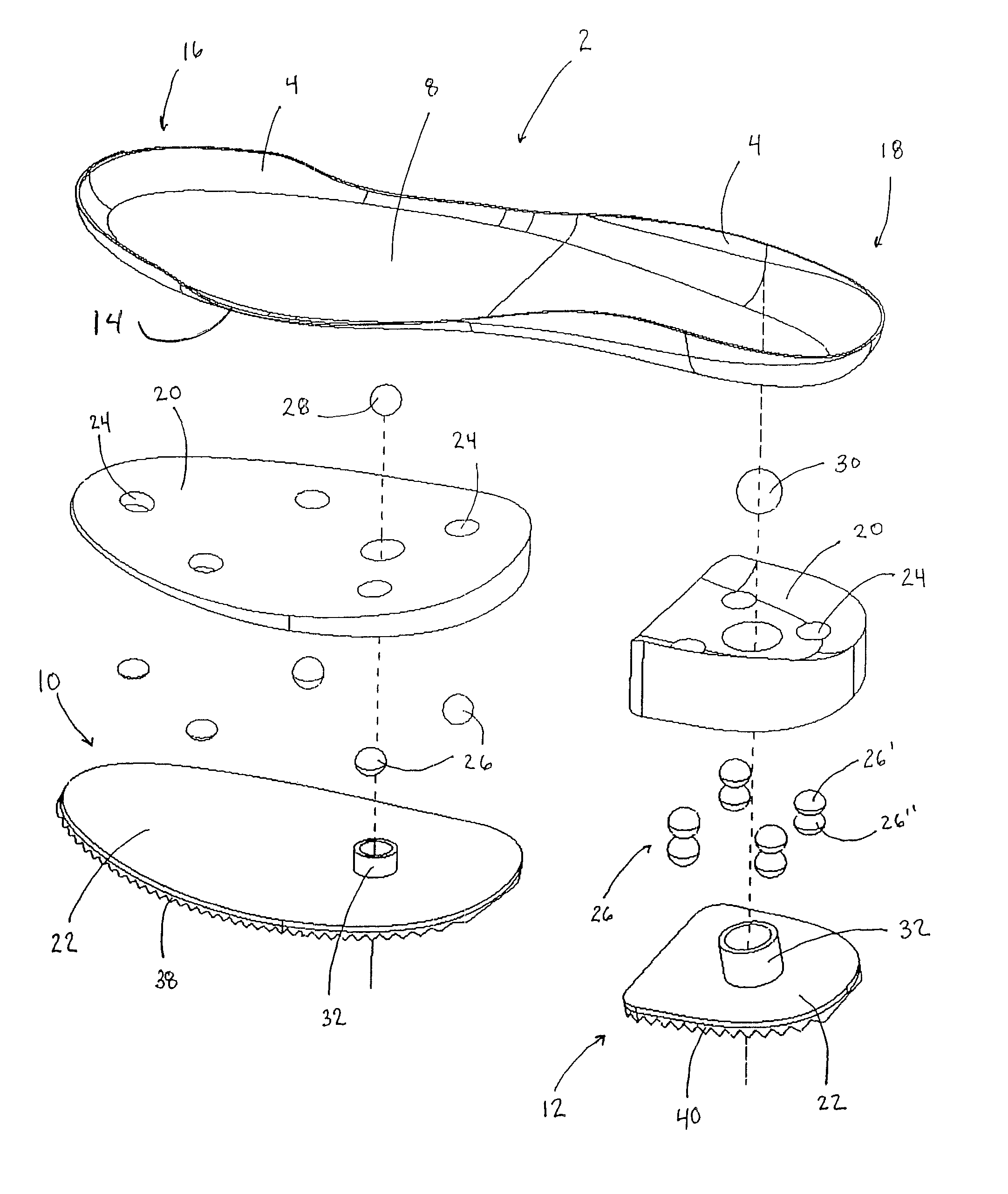
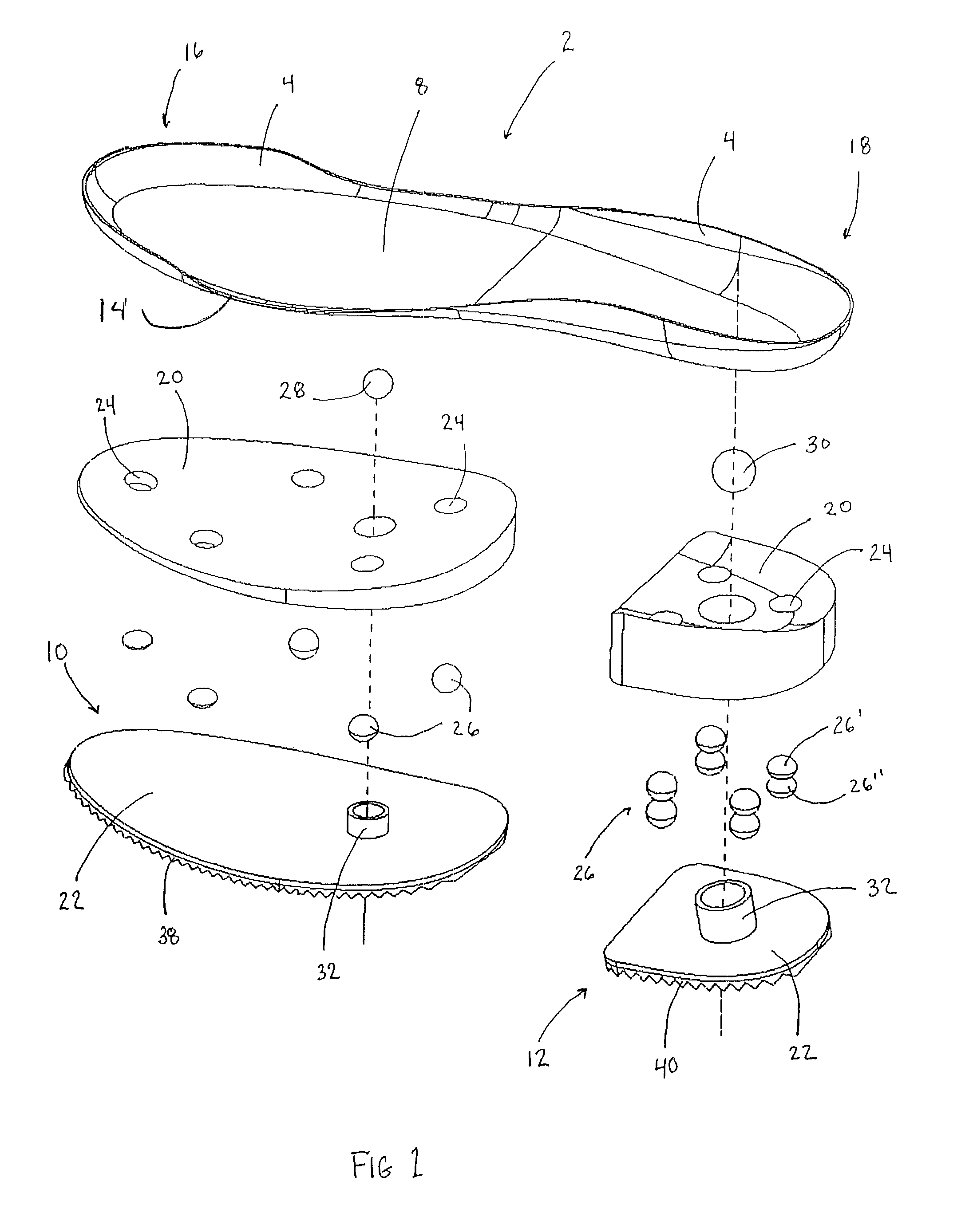
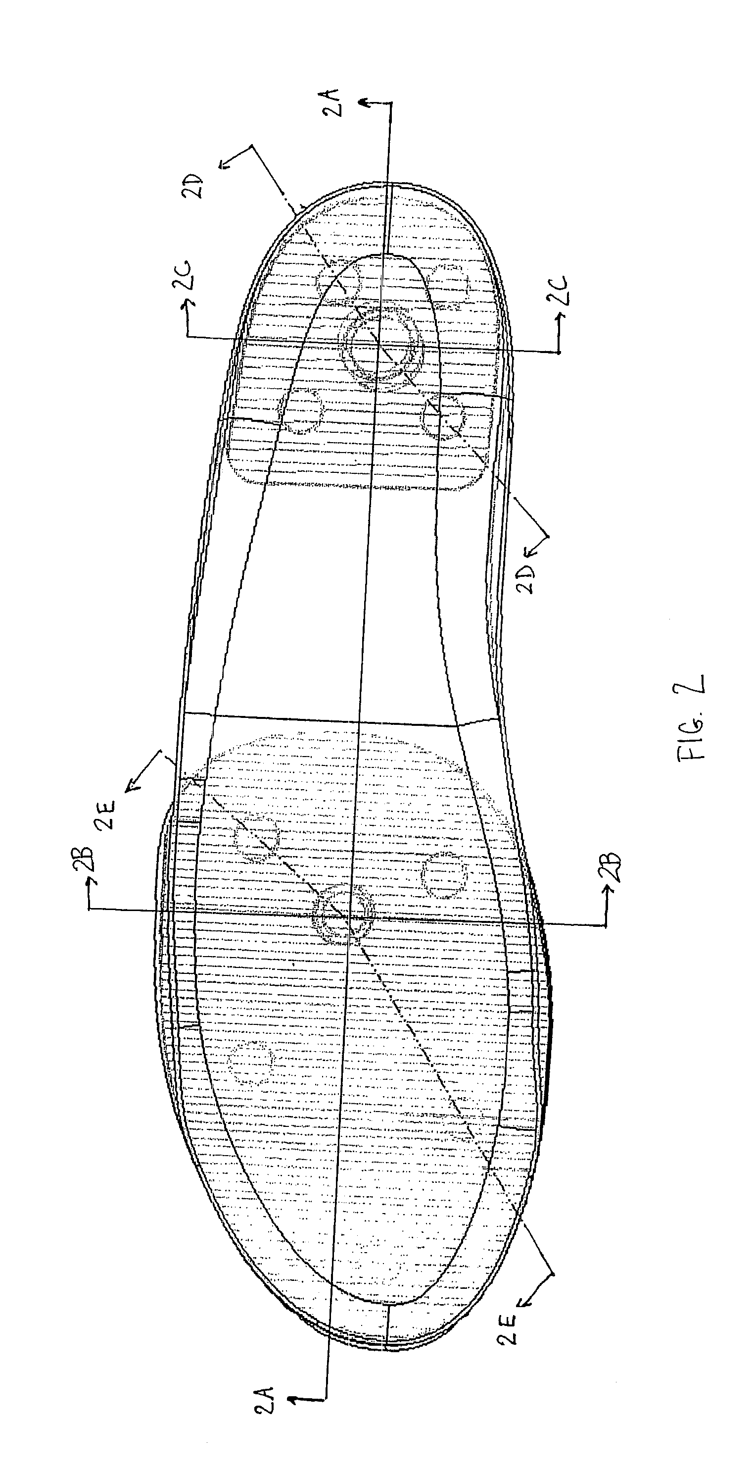
[0042]With reference now to FIGS. 1-2E, a detailed description concerning a first embodiment of the present invention will now be provided. As can be seen in these Figures, the foot engaging plate 2 generally comprises an elongate member which is adequately sized and shaped to support at least the heel, the arch and ball portions of a foot of a user. According to this embodiment, the foot engaging plate 2 is also sized to accommodate the toes of the user's foot and is provided with a substantially continuous contoured perimeter shroud or annular skirt 4 which helps maintain, support and retain the foot properly located and centered on the foot engaging plate 2 during use of the shoe sole 6. Preferably the foot engaging plate 2 is manufactured from a substantially rigid material, such as carbon fiber, a metal or some substantially rigid synthetic material which is designed to resist distortion and / or deflection of the foot engaging plate 2, during use thereof, so that the foot of the...


PUM

PropertyMeasurementUnit
thicknessaaaaaaaaaa
thicknessaaaaaaaaaa
thicknessaaaaaaaaaa

Abstract

A shoe sole comprising a foot engaging plate for accommodating a foot of a user and a ground engaging surface / plate. The foot engaging plate is sufficiently rigid so as to resist distortion of the foot engaging plate, during use of the shoe sole, so that the foot remains supported by the foot engaging plate during use of the shoe sole. A pivot member is located between the foot engaging plate and the ground engaging surface / plate to facilitate relative pivoting motion between the foot engaging plate and the ground engaging surface / plate. A layer of resilient material is sandwiched between the foot engaging plate and the ground engaging surface / plate. The resilient material may have one or more bores formed therein which accommodate a compressible material therein to facilitate programming of a desired compression characteristic for the shoe sole.

Description

FIELD OF THE INVENTION[0001]The present invention relates to improvements concerning shoe soles and, in particular to a shoe sole with at least one pivotal ground or surface engaging plate located therein.BACKGROUND OF THE INVENTION[0002]While a variety of shoe soles are known in the art, many of the current designs do not facilitate maintaining the foot in a properly oriented position during use of footwear or a shoe sole while the undersurface of the shoe sole is adapted to accommodate variations in the terrain upon which the footwear or shoe sole is being used. In addition, none of the footwear or shoe soles hereto known allows the internal structure of the shoe sole to be readily changed and / or programmed to suit a particular type of activity that the shoe sole will commonly experience.SUMMARY OF THE INVENTION[0003]Wherefore, it is an object of the present invention to overcome the above mentioned shortcomings and drawbacks associated with the prior art.[0004]Another object of t...

Claims


Application Information

Patent Timeline
Patent Type & Authority Patents(United States)
IPC IPC(8): A43B13/00A43B13/12
CPCA43B7/1415A43B13/12A43B13/141A43B13/16A43B13/186A43C15/16A43B13/125A43B13/14A43B13/145A43B13/18
Inventor HAY, GORDON G.ORR, KEITH M.CARROLL, DEREK
Owner ALINE SYST INC
Why Eureka
Try Eureka