Gripper

a technology of grippers and grippers, applied in fishing, hoisting equipment, manufacturing tools, etc., can solve the problems of inefficient packaging, high failure rate, inconvenient use, etc., and achieve the effect of quick and easy gripping of materials and quick and easy release of them

Active Publication Date: 2012-03-27
THE CHANTLAND PVS
View PDF9 Cites 13 Cited by
  • Summary
  • Abstract
  • Description
  • Claims
  • Application Information

AI Technical Summary

Benefits of technology

[0007]Another object of this invention is to provide a gripper, as aforesaid, that grips polywoven bags without damaging the material.
[0008]Still another object of this invention is to provide a gripper, as aforesaid, that quickly and easily grips the material and quickly and easily release it.
[0011]A still further object of this invention is to provide a gripper, as aforesaid, in which gripping plates may be easily repaired or replaced.

Problems solved by technology

While the existing devices are generally effective when used with cardboard or paper containers because of the smooth and generally non-pourous characteristics of those materials, the use of traditional bag placing equipment with woven materials, such as polywoven bags, results in high failure rates.
In other words, attempting to grip porous materials using suction technology results in unacceptable failure rates and, as a result, inefficient packaging.

Method used


Image

  • Gripper
  • Gripper
  • Gripper

Examples


Embodiment Construction

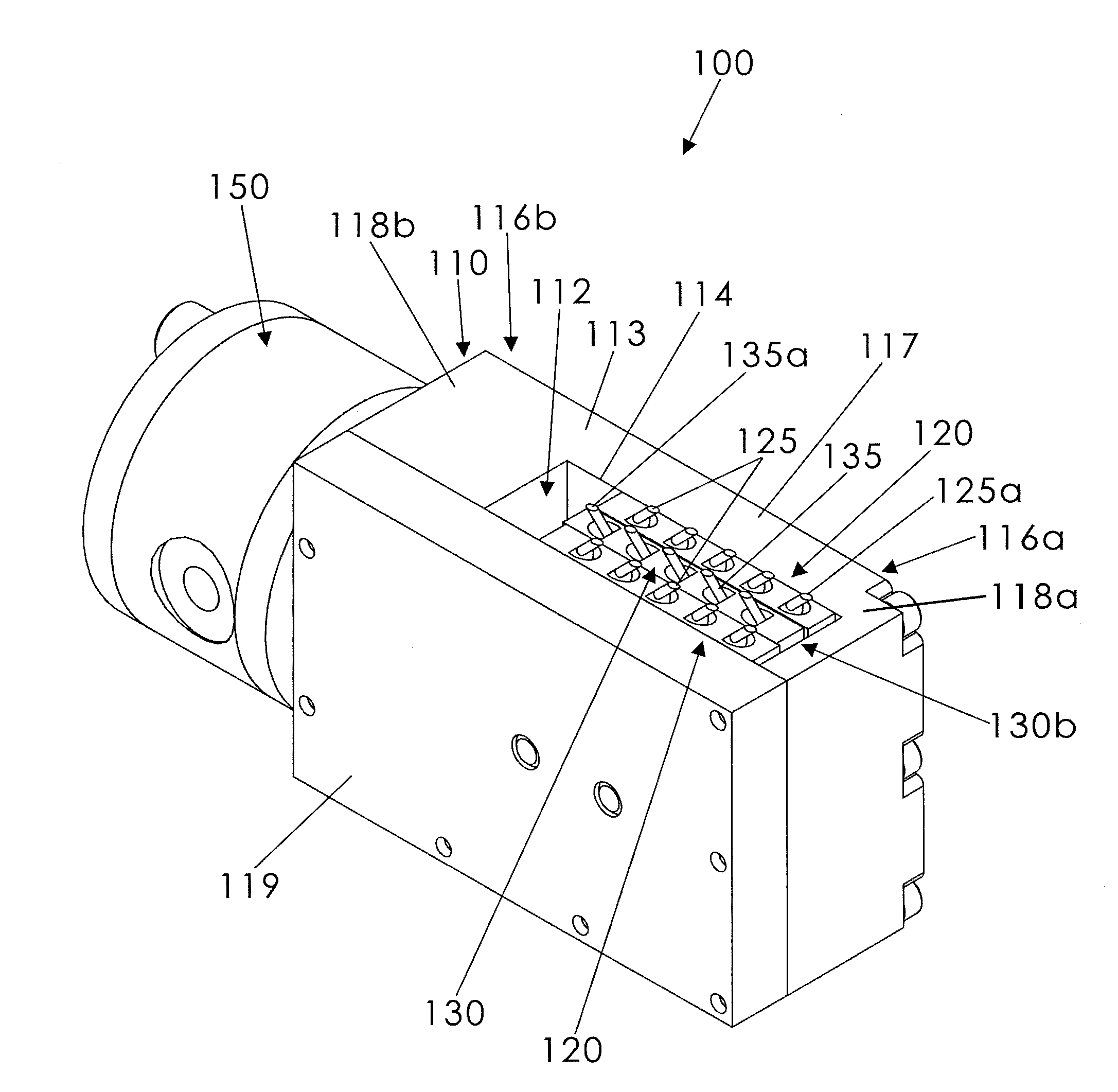
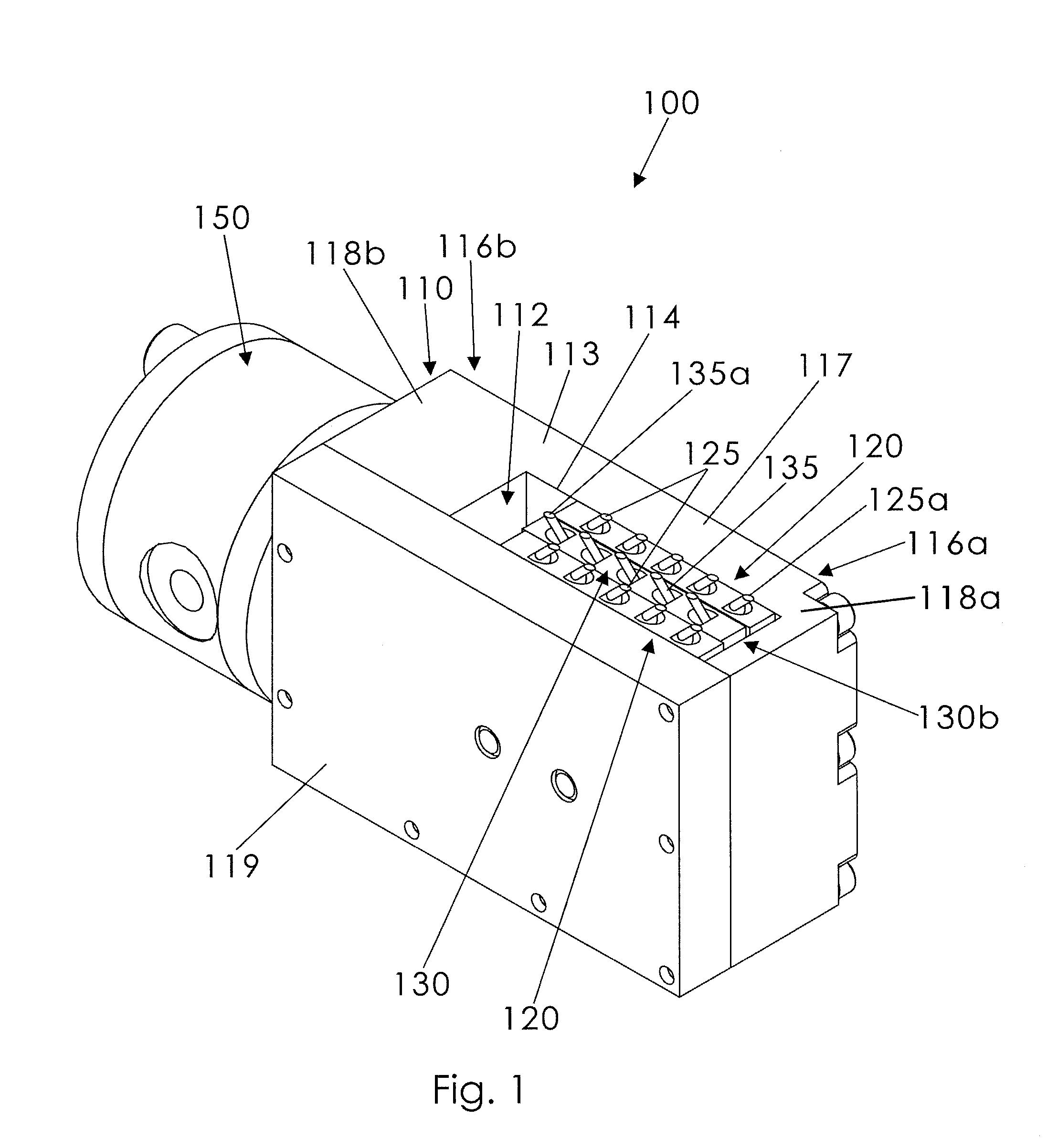
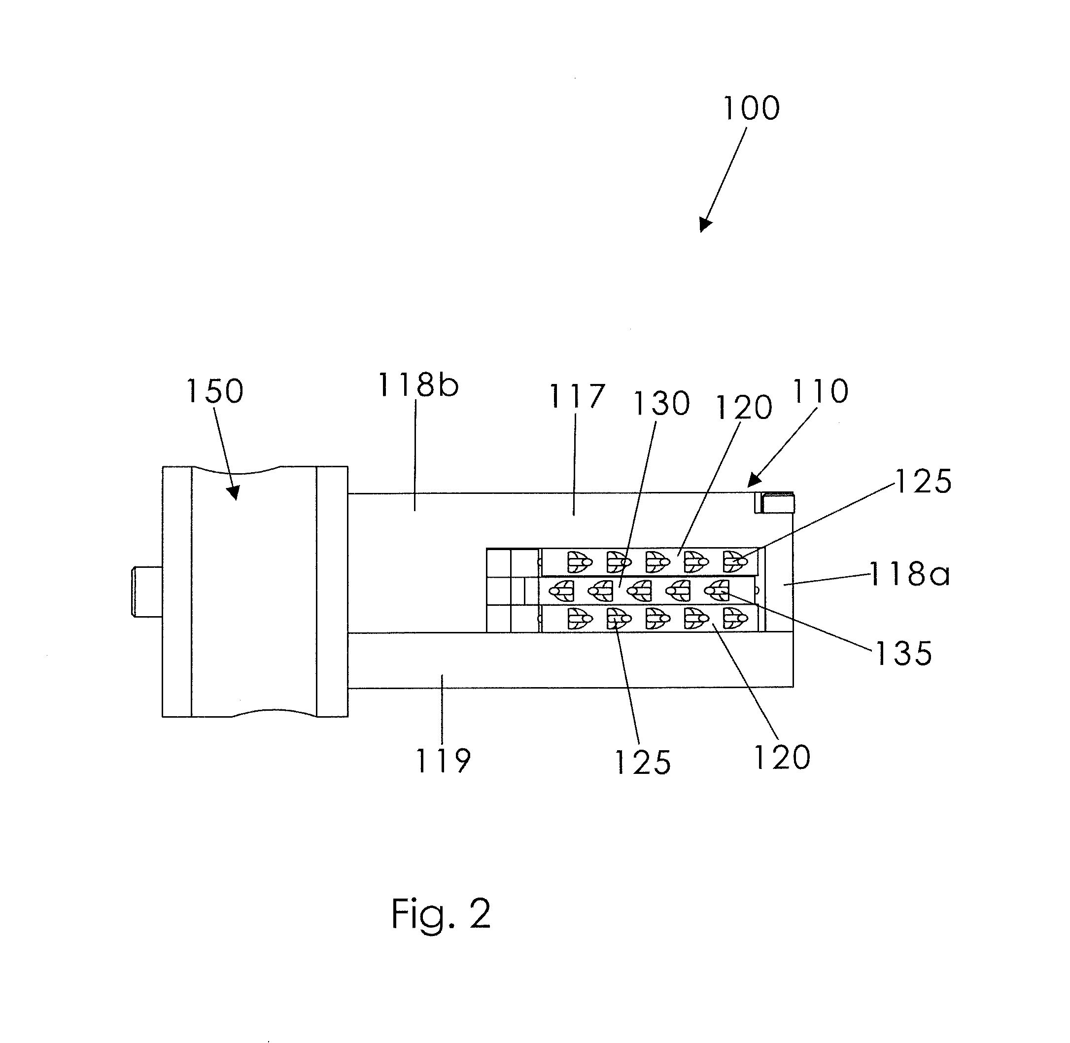
[0026]A gripper according to a preferred embodiment of the present invention will now be described in detail with reference to FIG. 1 through FIG. 11b of the accompanying drawings. More particularly, a gripper 100 includes a housing 110, a plurality of first hooks 125, and a plurality of second hooks 135.

[0027]As shown in FIG. 1, the housing 110 defines an open interior area 112 and has a generally planar work surface 113. The work surface 113 has an opening 114 to the interior area 112, and the housing 110 has opposed first and second ends 116a, 116b.

[0028]The first hooks 125 extend outwardly from the work surface 113 (i.e., away from the interior area past the work surface 113) toward the housing first end 116a, as shown in FIG. 1. The first hooks 125 may be generally linear and may be angled generally parallel to one another (FIG. 1). In some embodiments, as shown throughout the drawings, there are two rows of the first hooks 125.

[0029]A pair of outer stationary plates 120 may b...


PUM


Abstract

A gripper includes a housing defining an interior area and having a work surface, the work surface defining an opening to the interior area. The gripper includes a pair of outer stationary plates in the interior area that are fixed to the housing, each having a plurality of linear first hooks extending away from the work surface. The first hooks are angled parallel to one another and toward a housing first end. An inner plate is positioned in the interior area between the outer plates and includes linear second hooks extending away from the work surface. The second hooks are angled parallel to one another and opposite the first hooks. The inner plate is movable between a grip configuration and a release configuration. An actuator causes the inner plate to selectively move toward a housing second end to the grip configuration and toward the first end to the release configuration.

Description

BACKGROUND OF THE INVENTION[0001]This invention relates generally to gripping equipment and, more particularly, to a gripper for gripping a woven material, such as a polywoven material bag, without puncturing or otherwise damaging the bag.[0002]Bag placer devices are frequently used to prepare containers to be filled with other materials, such as solid, powder, or granular materials. Foods are often packaged in this way. The bag placer devices typically pull a container, such as a cardboard box or paper container, off of a stack, position it for filling, and separate two layers of material so as to open the container. The most typical means for placing and opening a container for filling is suction or vacuum technology. More particularly, suction devices create a seal between a gripping component and the material surface so as to enable the entire container to be lifted or for opposing surfaces to be moved away from one another to open the container for filling.[0003]While the exist...

Claims


Application Information

Patent Timeline
Patent Type & Authority Patents(United States)
IPC IPC(8): A01K81/04
CPCB25J15/0071B65B43/30
Inventor BUTLER, BRADLEY A.BEAUCHAMP, JACK E.
Owner THE CHANTLAND PVS
Why Eureka
Try Eureka