
Method and system for shot tracking

a shot tracking and tracking method technology, applied in the field of shot tracking, can solve the problems of lack of a method and a system to measure in the early art, and achieve the effects of improving the antenna function, improving the accuracy of location measurement, and low power of the radar wav

Active Publication Date: 2012-03-27
TOPGOLF CALLAWAY BRANDS CORP
View PDF19 Cites 21 Cited by
  • Summary
  • Abstract
  • Description
  • Claims
  • Application Information

AI Technical Summary

Benefits of technology

The present invention is a new technology for measuring the motion of a golf club during a swing. It uses a coherent pattern to capture the position of the club relative to a fixed device. This information is processed to display the swing and calculate the flight of the ball. The invention can be installed in both permanent and interchangeable shafts and uses two antennas to measure the speed and motion of the swing. It improves training and practice results for golfers by accurately measuring the swing and producing a display of the impact and ball flight.

Problems solved by technology

The prior art is lacking in a method and system to measure the motion of the club through measurement of the shaft.

Method used


Image

  • Method and system for shot tracking
  • Method and system for shot tracking
  • Method and system for shot tracking

Examples


Embodiment Construction

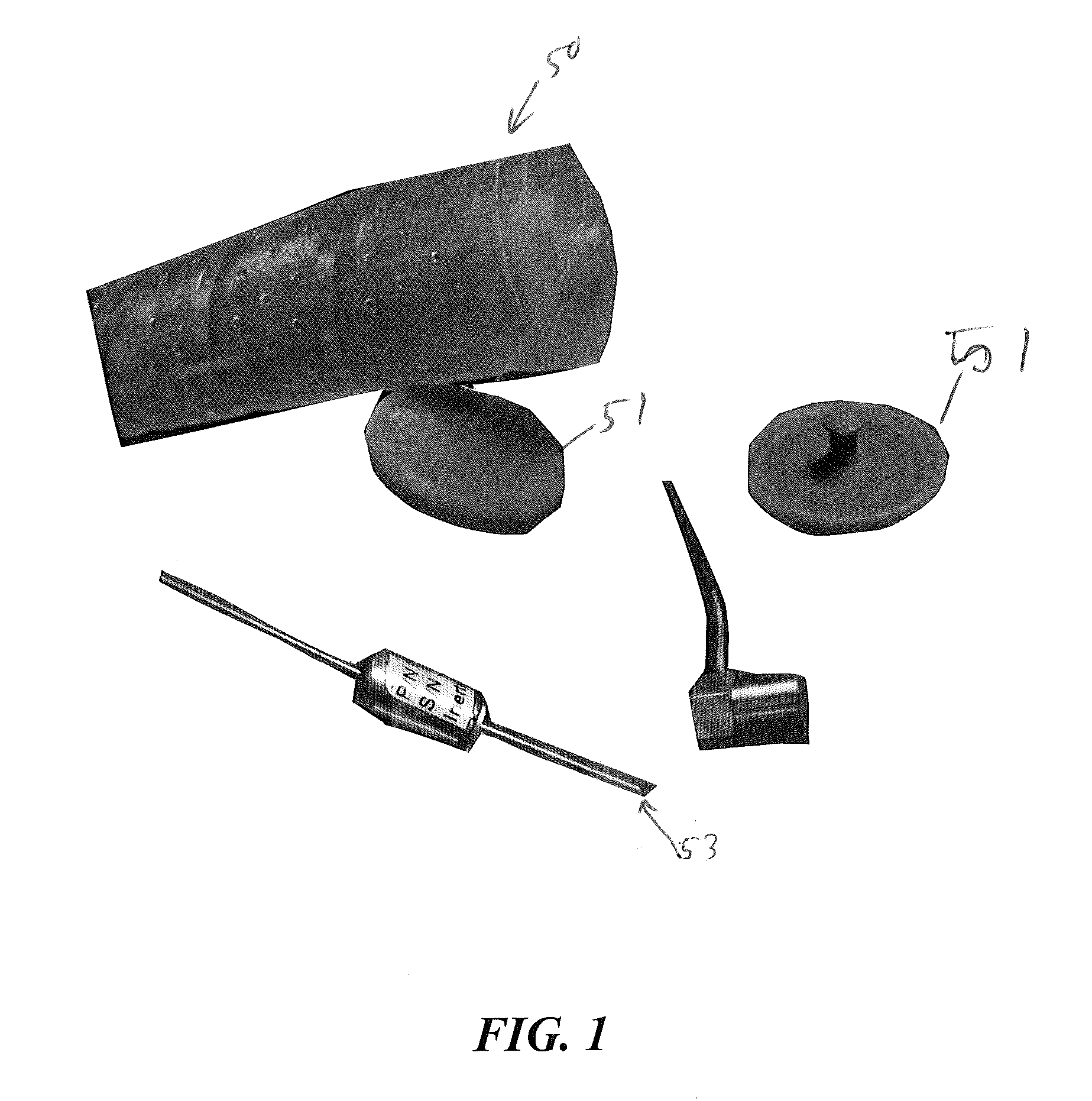
[0020]As shown in FIG. 1, components of the system can be attached to a golf club. Alternatively, the components can be integrated into a golf club.

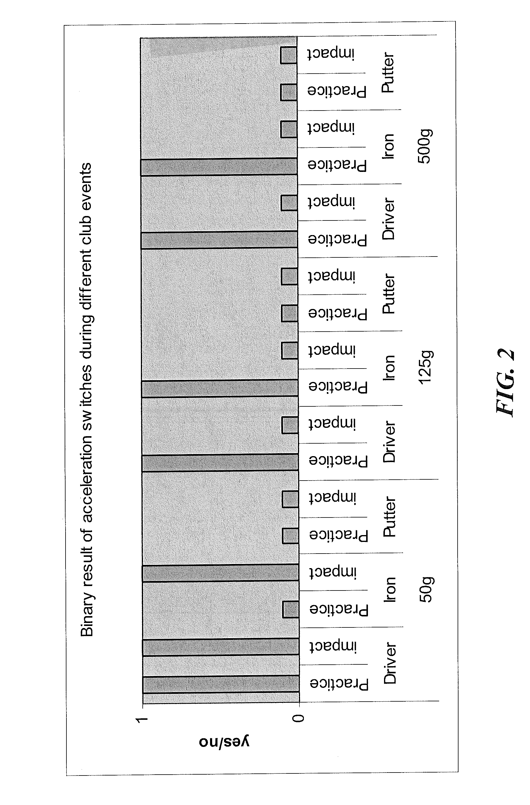
[0021]FIG. 2 shows that different levels of acceleration switches can be effectively used to detect that a golf club has been used during by a golfer. A 50 g switch, a 125 g switch and a 500 g switch were used for this testing.

[0022]FIG. 3 shows the levels detected during a golf club impact with a golf ball.

[0023]FIG. 4 illustrates a portion of a golf club 50. The components of the system 20 within the golf club 50 preferably include an active RFID transponder 51, a power source 52, a switch 53 and an accelerometer 54. Those skilled in the pertinent art will recognize that the accelerometer and switch may be a single device.

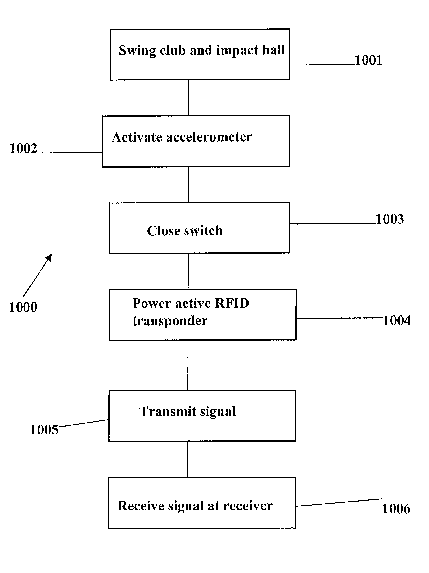
[0024]FIG. 5 is a flow chart of a method 1000 for shot tracking. At block 1001, a golfer swings a club and impacts a golf ball. At block 1002, an accelerometer is activated by the impact of the golf club with the golf...


PUM


Abstract

A system and method for shot tracking disclosed herein. The system preferably includes a golf club and a receiver. The golf club preferably includes an active RFID transponder, a power source, a switch and an accelerometer.

Description

CROSS REFERENCES TO RELATED APPLICATIONS[0001]The Present Application claims priority upon U.S. Provisional Application No. 61 / 22983, filed Jul. 30, 2009.STATEMENT REGARDING FEDERALLY SPONSORED RESEARCH OR DEVELOPMENT[0002]Not ApplicableBACKGROUND OF THE INVENTION[0003]1. Field of the Invention[0004]The present invention relates to shot tracking. More specifically, the present invention relates to a method and system for tracking shots of a golfer during a round of golf.[0005]2. Description of the Related Art[0006]Golf clubs combine with the players swing to propel a ball toward a favored location and through a favored path. The orientation and speed of the club head at impact largely determines the ball path including carry distance and roll.[0007]The prior art is lacking in a method and system to measure the motion of the club through measurement of the shaft.BRIEF SUMMARY OF THE INVENTION[0008]The present invention is novel in that the observation of the relative motion does not ...

Claims


Application Information

Patent Timeline
Patent Type & Authority Patents(United States)
IPC IPC(8): A63B69/36
CPCA63B24/0021A63B69/3658A63B69/3614A63B69/3632A63B2024/0031A63B2024/0037A63B2220/12A63B2220/40A63B2220/51A63B2220/58A63B2220/801A63B2220/833A63B2220/89A63B2225/54
Inventor BALARDETA, JOSEPHDENTON, SCOTT
Owner TOPGOLF CALLAWAY BRANDS CORP
Learn More