Network switch that is optimized for a telephony-capable endpoint

a network switch and endpoint technology, applied in the field of telecommunications, can solve the problems of unnecessarily restricting other connected devices to exchange data with the packet network at the lower rate, and the processor of the phone is often incapable of handling flood data rate, so as to achieve a much higher traffic rate and greater processing capability

Active Publication Date: 2012-03-27
AVAYA INC
View PDF13 Cites 2 Cited by
  • Summary
  • Abstract
  • Description
  • Claims
  • Application Information

AI Technical Summary

Benefits of technology

[0014]In accordance with the illustrative embodiment, the enhanced network switch receives signals from two or more devices being that are connected to the switch, as part of the auto-negotiation process. In some circumstances, the switch sets the speed of the link with the upstream device to the lowest rate supported. Selecting the lowest rate is based on the presence of a particular network element, such as a phone with a marginal processor, or on a device being plugged into a particular port, such as a port marked “phone”. In some embodiments, when a third network element such as a personal computer is connected to the network switch, the auto-negotiation rules in the prior art can override the rules of the illustrative embodiment; in this way, the third network element is not penalized in terms of the allowable data rate of packets from the packet network. In some other embodiments, the receive-path link from the upstream device of a full-duplex link can be set to the lowest rate to prevent processor overload, while the transmit-path link can independently be set at the highest rate without an adverse effect on the phone's processor.

Problems solved by technology

However, when the phone is struck with a packet flood, the phone's processor is often incapable of handling the flood data rate, even though the phone's network interface is still able to handle the flood data rate.
Unfortunately, the prior-art technique has the disadvantage of unnecessarily constraining other connected devices to exchange data with the packet network at the lower rate.

Method used


Image

  • Network switch that is optimized for a telephony-capable endpoint
  • Network switch that is optimized for a telephony-capable endpoint
  • Network switch that is optimized for a telephony-capable endpoint

Examples


Embodiment Construction

[0021]The term “network element,” and its inflected forms, is defined for use in this specification, including the appended claims, as a telecommunications device that is addressable. A network element can be an endpoint device such as a packet-based telephone, a host device such as a computer server, or a networking device such as a switch or router.

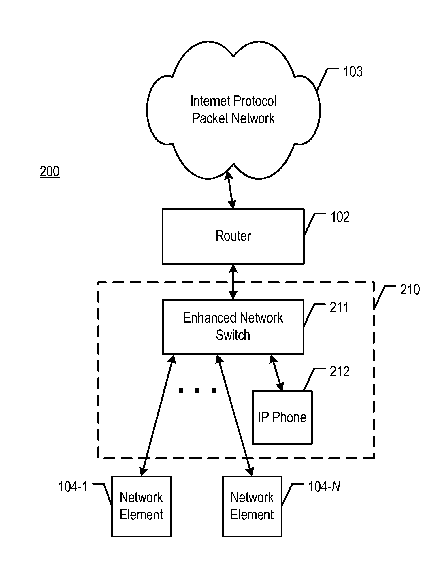
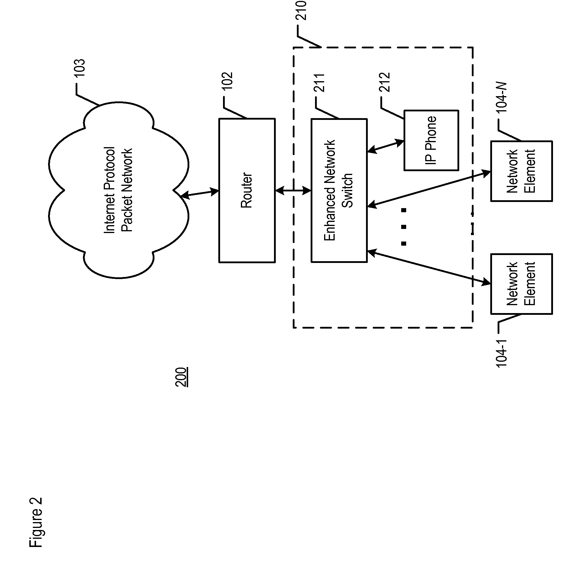
[0022]FIG. 2 depicts telecommunication system 200, in accordance with the illustrative embodiment of the present invention. System 200 comprises router 102, Internet Protocol (IP) packet network 103, and network elements 104-1 through 104-N, wherein N is a positive integer, as well as enhanced network switch 211 and IP-capable phone 212. The elements depicted in FIG. 2 are interconnected as shown. Router 102, IP packet network 103, and network elements 104-1 through 104-N are described above and with respect to FIG. 1.

[0023]Two types of networks are represented in FIG. 2. The first is an Internet Protocol (IP) packet network, which is d...


PUM


Abstract

A method is disclosed that enables the avoidance of a processor overload of a telecommunications endpoint device that is susceptible to traffic floods. An enhanced network switch sets the speed on one of its data ports as a specific function of the speeds of the devices that are connected to one or more of its other data ports. This behavior is different from that of network switches in the prior art, in which the data rate of a port in the prior art is auto-negotiated to the highest speed that can be supported by the network elements at either end of the port's connection, regardless of the other devices present. By considering the specific devices that are connected, the enhanced network switch is able to limit the amount of traffic that is directed by an upstream device, such as a router, towards a device with limited processor capability, such as a packet-based phone.

Description

FIELD OF THE INVENTION[0001]The present invention relates to telecommunications in general, and, more particularly, to mitigating the effects of a packet attack on a telephony-capable endpoint that is connected to a network switch.BACKGROUND OF THE INVENTION[0002]FIG. 1 depicts a schematic diagram of telecommunications system 100 in the prior art. System 100 routes voice conversations, or other types of media such as video, between telephony-capable network elements such as telephones. System 100 comprises network switch 101, router 102, Internet Protocol packet network 103, and endpoint network elements 104-1 through 104-M, wherein M is a positive integer. The elements depicted in FIG. 1 are interconnected as shown. In FIG. 1, two types of networks are represented: an Internet Protocol (IP) packet network, which is depicted by network 103, and a local area network (or “LAN”), which comprises network switch 101 and the network elements that are connected to the switch.[0003]Network ...

Claims


Application Information

Patent Timeline
Patent Type & Authority Patents(United States)
IPC IPC(8): H04L12/26H04L47/22H04L49/111
CPCH04L47/10H04L47/22H04L49/3054
Inventor ADHIKARI, AKSHAYGARG, SACHINKRISHNAKUMAR, ANJUR SUNDARESANSINGH, NAVJOT
Owner AVAYA INC
Why Eureka
Try Eureka