Hydraulic tool

a technology of hydraulic tools and gear pullers, which is applied in the field of hydraulic tools, can solve the problems of increasing the cost of buying more gear pullers and the restricted application scope of gear pullers, and achieves the effect of enhancing applicability and flexibility

Inactive Publication Date: 2012-04-03
HUNG JUNG LIANG
View PDF7 Cites 26 Cited by
  • Summary
  • Abstract
  • Description
  • Claims
  • Application Information

AI Technical Summary

Benefits of technology

[0006]The present invention provides a hydraulic tool which is enhanced in applicability and flexibility by being capable of performing an external-pulling or an internal pulling operation for an object to be assembled or disassembled.

Problems solved by technology

Therefore, disassembling different types of components requires the use of different gear pullers, which not only increases the cost for buying more gear pullers, but also the gear puller is also restricted in application scope.

Method used


Image

  • Hydraulic tool
  • Hydraulic tool
  • Hydraulic tool

Examples


Embodiment Construction

[0035]The present invention will be clearer from the following description when viewed together with the accompanying drawings, which show, for purpose of illustration only, the preferred embodiments in accordance with the present invention.

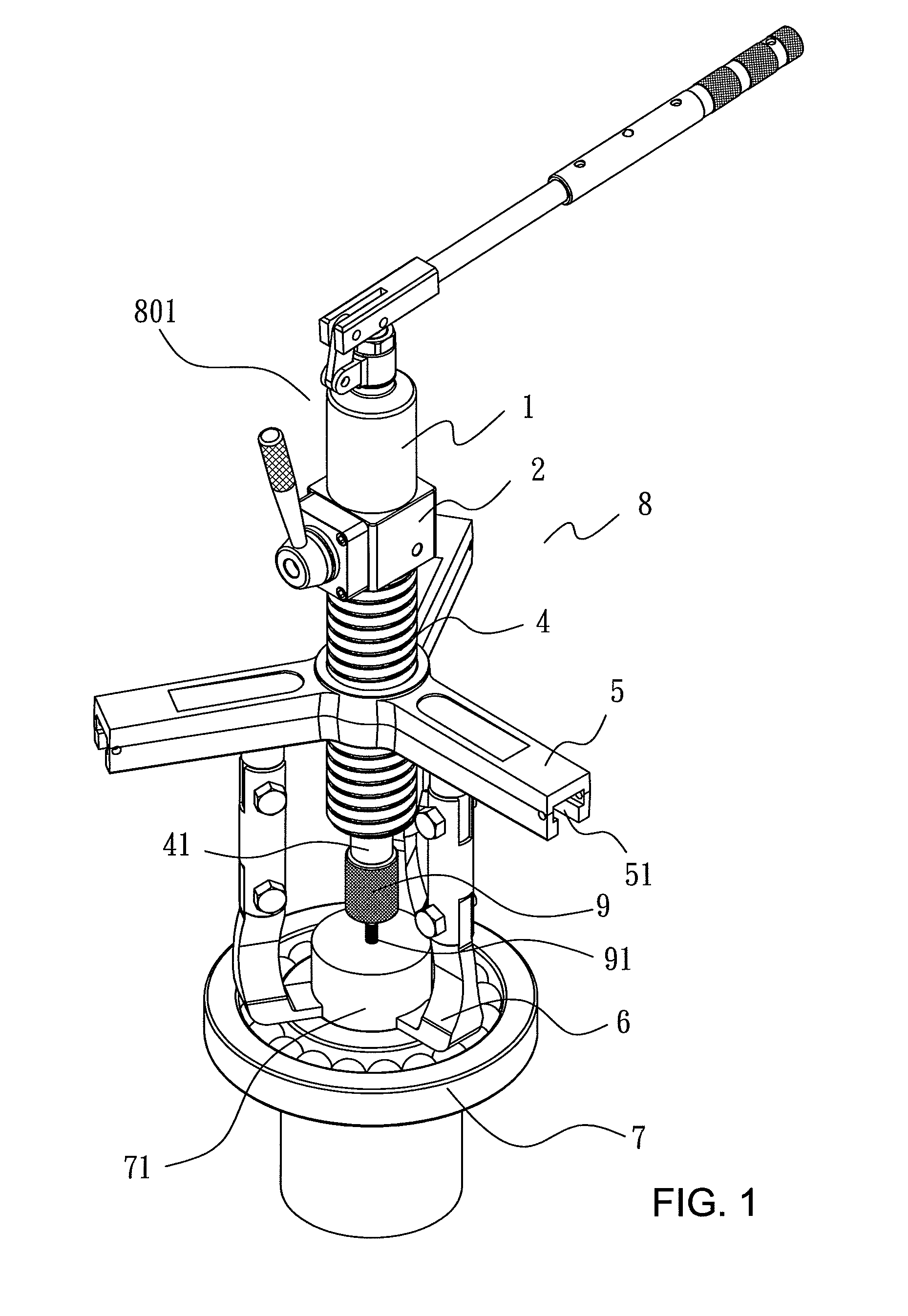
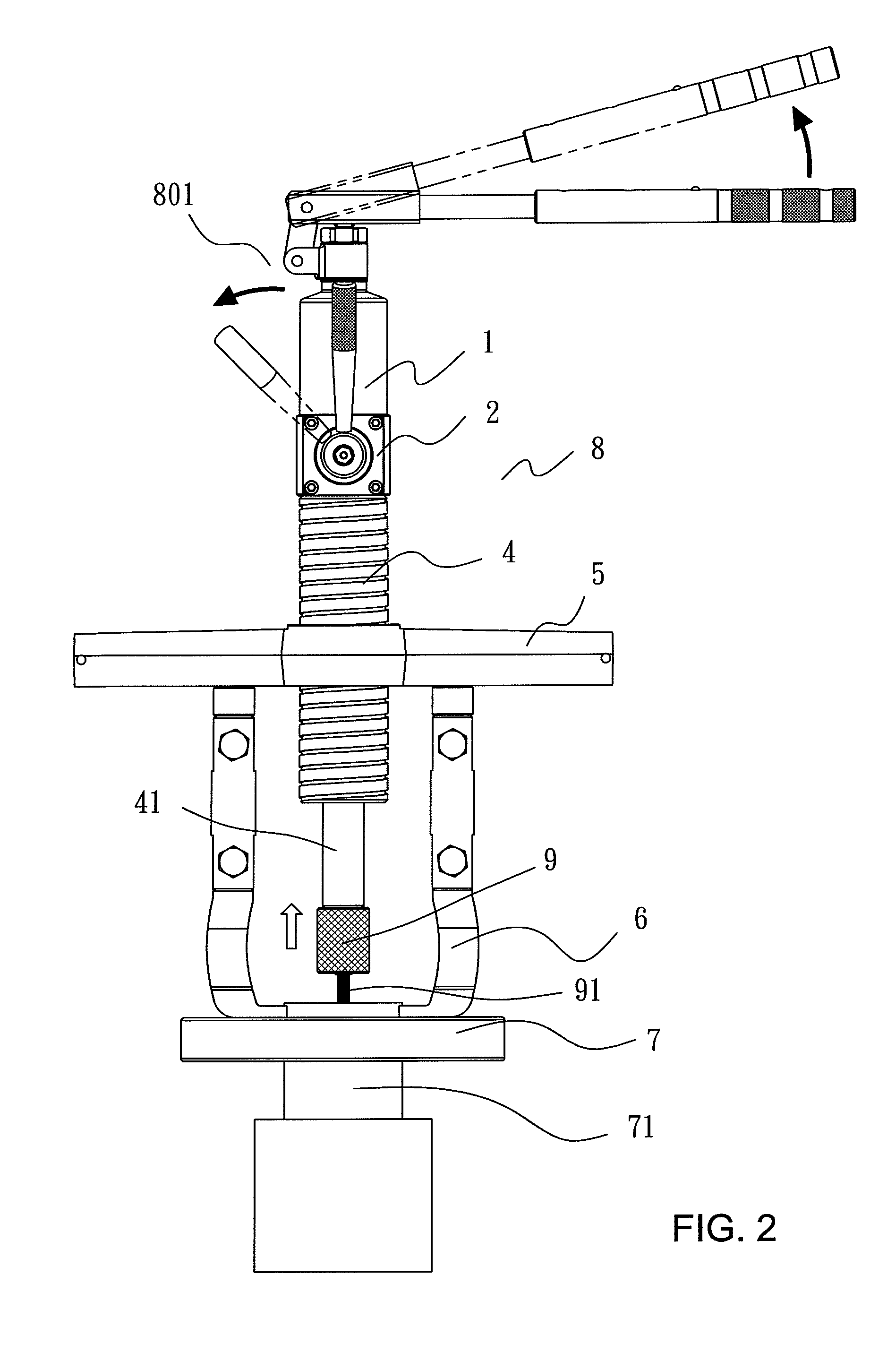
[0036]Referring to FIGS. 1 and 2, a hydraulic tool 8 in accordance with the present invention which is capable of performing external-pulling or internal-pulling operation for an object to be assembled or disassembled comprises a control valve 2 with one end connected with an oil storage member 1. The other end of the control valve 2 is connected with an oil pressure tank 3 which is provided with an adjustment threaded portion 4 on the outer surface thereof. Screwed on the adjustment threaded portion 4 is a bracket 5 with a plurality of radially-arranged slide rails 51 facing downward. Plural clamping jaws 6 with articulated joints are disposed in the respective slide rails 51, and disposed at one end of the oil storage member 1 is a hand-operate...


PUM

PropertyMeasurementUnit
pressureaaaaaaaaaa
flexibilityaaaaaaaaaa
timeaaaaaaaaaa

Abstract

A hydraulic tool for assembling and disassembling components, such as gears, bearings, etc. of a shaft, is capable of performing an external-pulling or an internal-pulling operation as desired for an object to be assembled or disassembled. The hydraulic tool includes an oil pressure assembly having a hand-operated pump, an oil storage member, a control valve, an oil pressure tank, a set of external pulling type clamping jaws, internal pulling type clamping jaws, and a bolt for assembling purpose. The hydraulic tool has high mobility and portability, is capable of performing assembling or disassembling operations at any angle and position, and is considerably enhanced in applicability.

Description

BACKGROUND OF THE INVENTION[0001]1. Field of the Invention[0002]The present invention relates to a hydraulic tool and, more particularly, to a hydraulic tool for assembling and disassembling components (such as gears, bearings, etc.) of a shaft, and which is capable of performing an external-pulling or an internal pulling operation for an object to be assembled or disassembled.[0003]2. Description of the Prior Art[0004]The current gear puller for disassembling components (such as gears, bearings, etc.) disposed on the shaft usually has only a single function (for example, a function of performing an external-pulling or an internal-pulling operation for pulling out a component). Therefore, disassembling different types of components requires the use of different gear pullers, which not only increases the cost for buying more gear pullers, but also the gear puller is also restricted in application scope.[0005]The present invention has arisen to mitigate and / or obviate the afore-descri...

Claims


Application Information

Patent Timeline
Patent Type & Authority Patents(United States)
IPC IPC(8): B23P19/04B25B27/00B25B27/14B23Q3/08
CPCB25B27/026B25B27/064Y10T29/53909Y10T29/5383Y10T29/53943Y10T29/53843Y10T29/53796
Inventor HUNG, JUNG-LIANG
Owner HUNG JUNG LIANG
Why Eureka
Try Eureka