Base station, base station positioning method and corresponding equipment
A base station positioning and base station technology, applied in location information-based services, electrical components, wireless communications, etc., can solve the problems of complex positioning calculation methods and limited base station positioning accuracy, and achieve the effect of improving accuracy and simplifying calculation logic
- Summary
- Abstract
- Description
- Claims
- Application Information
AI Technical Summary
Problems solved by technology
Method used
Image
Examples
Embodiment 1
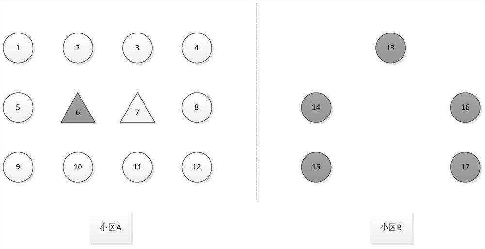
[0046] refer to figure 1 , each independent shape in the figure indicates each independent base station, and different shapes refer to the status of the position calibration of the base station, wherein, the solid circle (●) refers to an unmarked normal base station, and the hollow circle (○) Refers to the calibrated normal base station, the solid triangle (▲) refers to the uncorrected abnormal base station, and the hollow triangle (△) refers to the corrected abnormal base station. Further, with the dotted line in the middle as the dividing line, the left half area is defined as cell A, and the right half area is defined as cell B, and cell A and cell B are adjacent to each other, and there is no overlapping area.
[0047] Taking cell A as an example, the base station positioning method of this application is described in detail.
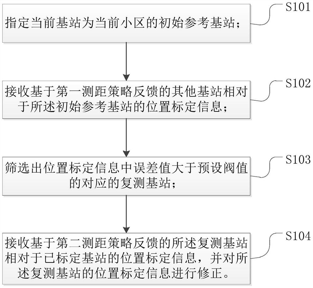
[0048] refer to figure 2 , the base station positioning method of the present application includes the following steps:
[0049] S101, specifyi...
Embodiment 2
[0091] continue to refer figure 1 , each independent shape in the figure indicates each independent base station, and different shapes refer to the status of the position calibration of the base station, wherein, the solid circle (●) refers to an unmarked normal base station, and the hollow circle (○) Refers to the calibrated normal base station, the solid triangle (▲) refers to the uncorrected abnormal base station, and the hollow triangle (△) refers to the corrected abnormal base station. Further, with the dotted line in the middle as the dividing line, the left half area is defined as cell A, and the right half area is defined as cell B, and cell A and cell B are adjacent to each other, and there is no overlapping area.
[0092] Taking cell A as an example, the base station positioning method of this application is described in detail.
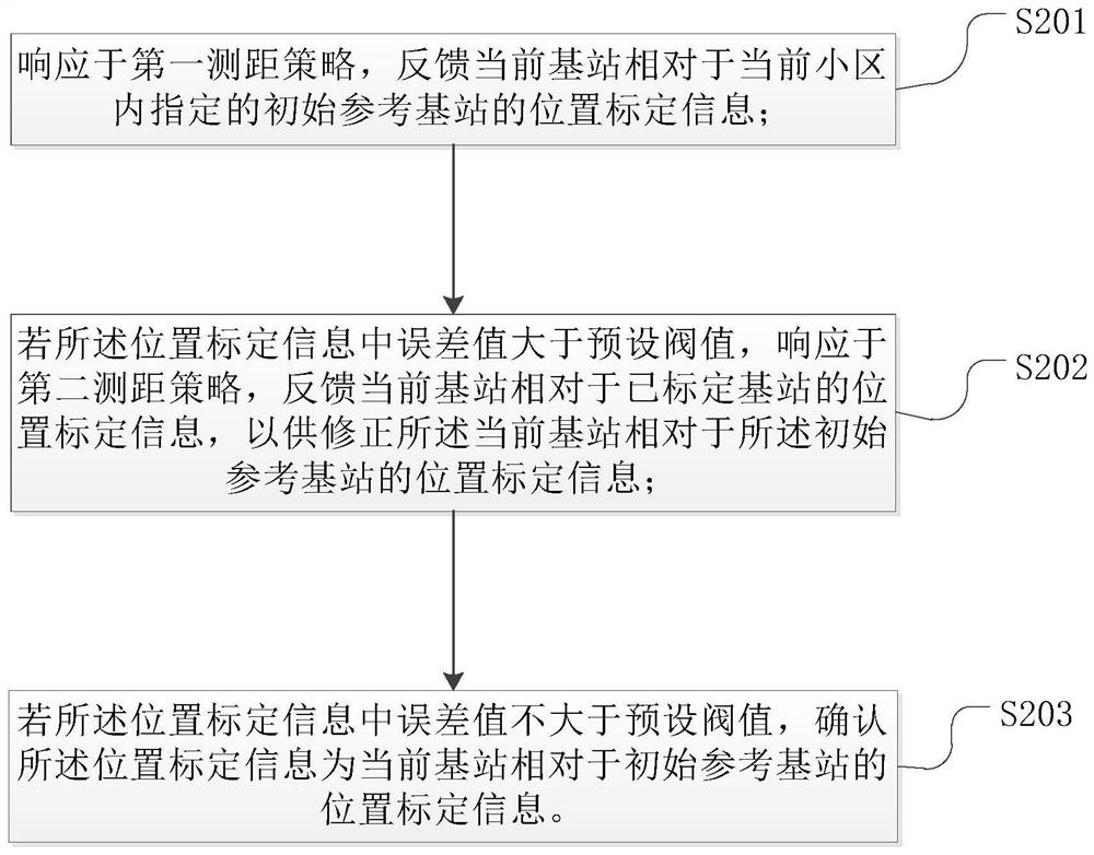
[0093] refer to image 3 , the base station positioning method of the present application includes the following steps:
[0094] S201, ...
Embodiment 3
[0102] continue to refer figure 1 , with the dotted line in the middle as the dividing line, the left half area is defined as cell A, and the right half area is defined as cell B, cell A and cell B are adjacent to each other, and there is no overlapping area. According to the actual situation, the division principle of cell A and cell B tends to be artificial, but it does not rule out the principle based on signal coverage. There are two adjacent and non-overlapping cells, and the non-overlapping cells use this application The technical scheme has more outstanding advantages. Such as figure 1 In the state shown, in the process of confirming the position calibration information one by one by the base stations in the cell A, each base station in the cell B is in an unmarked state, and the base stations 13-17 in the cell B are all uncalibrated normal base stations ( ●).
[0103] For the base station in cell B, its positioning method can choose one of the following methods:
...
PUM
 Abstract
Description
Claims
Application Information
 - R&D
- Intellectual Property
- Life Sciences
- Materials
- Tech Scout
- Unparalleled Data Quality
- Higher Quality Content
- 60% Fewer Hallucinations
Browse by: Latest US Patents, China's latest patents, Technical Efficacy Thesaurus, Application Domain, Technology Topic, Popular Technical Reports.
© 2025 PatSnap. All rights reserved.Legal|Privacy policy|Modern Slavery Act Transparency Statement|Sitemap|About US| Contact US: help@patsnap.com


