Support arrangement of roll in fibrous-web machine

a technology of fibrous web and support arrangement, which is applied in the direction of machine supports, furniture parts, manufacturing tools, etc., can solve the problems of large space occupation, poor damping effect, and large vibration of rolls,

Active Publication Date: 2012-04-03
VALMET TECH INC
View PDF22 Cites 3 Cited by
  • Summary
  • Abstract
  • Description
  • Claims
  • Application Information

AI Technical Summary

Benefits of technology

[0010]With this arrangement, such an effect is achieved that in the support the dampening of vibration is provided effective without endangering the rigidity of the support in such directions which require rigidity.
[0011]A direction control arrangement of a support arrangement of a roll according to an embodiment of the invention comprises at least one support part which is fastened in both the first frame part and the second frame part. The support part is arranged according to the invention substantially perpendicular in relation to the direction allowed by elasticity and it is thin in the direction allowed by elasticity. A support part arranged this way prevents the mutual motion of the first piece and the second piece mainly in other than the substantially perpendicular direction in relation to the plane of the support part.

Problems solved by technology

The vibration of rolls is a great problem with present-day fibrous-web machines, inter alia, due to the increase in operating speed.
In these, the damper is outside the roll, whereby it, inter alia, occupies considerable space.
This kind of an arrangement does not always provide good enough damping.
A problem of such an arrangement is, however, that simultaneously as the critical speed ranges are changed by making the support elastic, the static rigidity of the support suffers.
Particularly in such an arrangement, the static rigidity of the support also weakens in such directions in which it is not desired.
This causes problems particularly in targets demanding accurate setting, such are e.g. nip contacts between the rolls and between the roll and the web reel.
A problem of the arrangement presented in this specification is also that making the support more elastic causes easily that elasticity, particularly its direction, is not sufficiently controlled.

Method used


Image

  • Support arrangement of roll in fibrous-web machine
  • Support arrangement of roll in fibrous-web machine
  • Support arrangement of roll in fibrous-web machine

Examples


Embodiment Construction

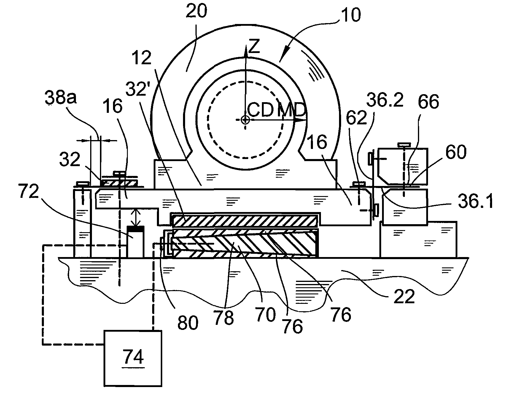
[0028]The rolls of the fibrous-web machine are typically supported from their ends in the frame or foundation of the machine. The structure of the roll can be such that it comprises a hollow shell and heads arranged to its ends in which head there further is a quite short shaft. Such a roll is rotatably supported by the above-mentioned shafts in the frame or foundation of the machine. The structure of the roll can also be such that it comprises a frame stationary when operated supportable to the frame from its ends and a shell rotatably arranged around it. In such a roll, the shell can even be to some extent elastic, and a shoe has been arranged inside it to support the shell, whereby the roll is often called a long-nip roll.

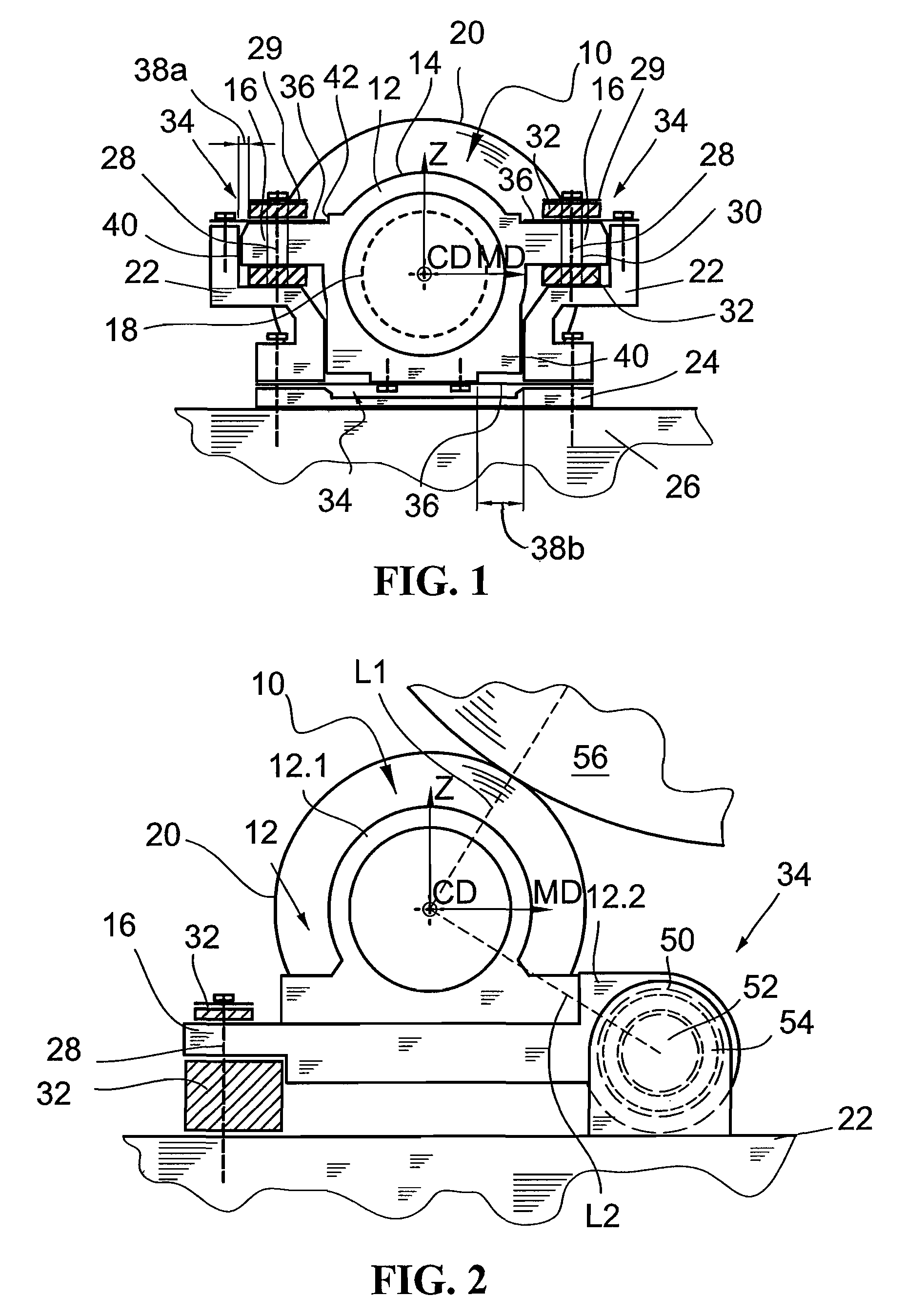
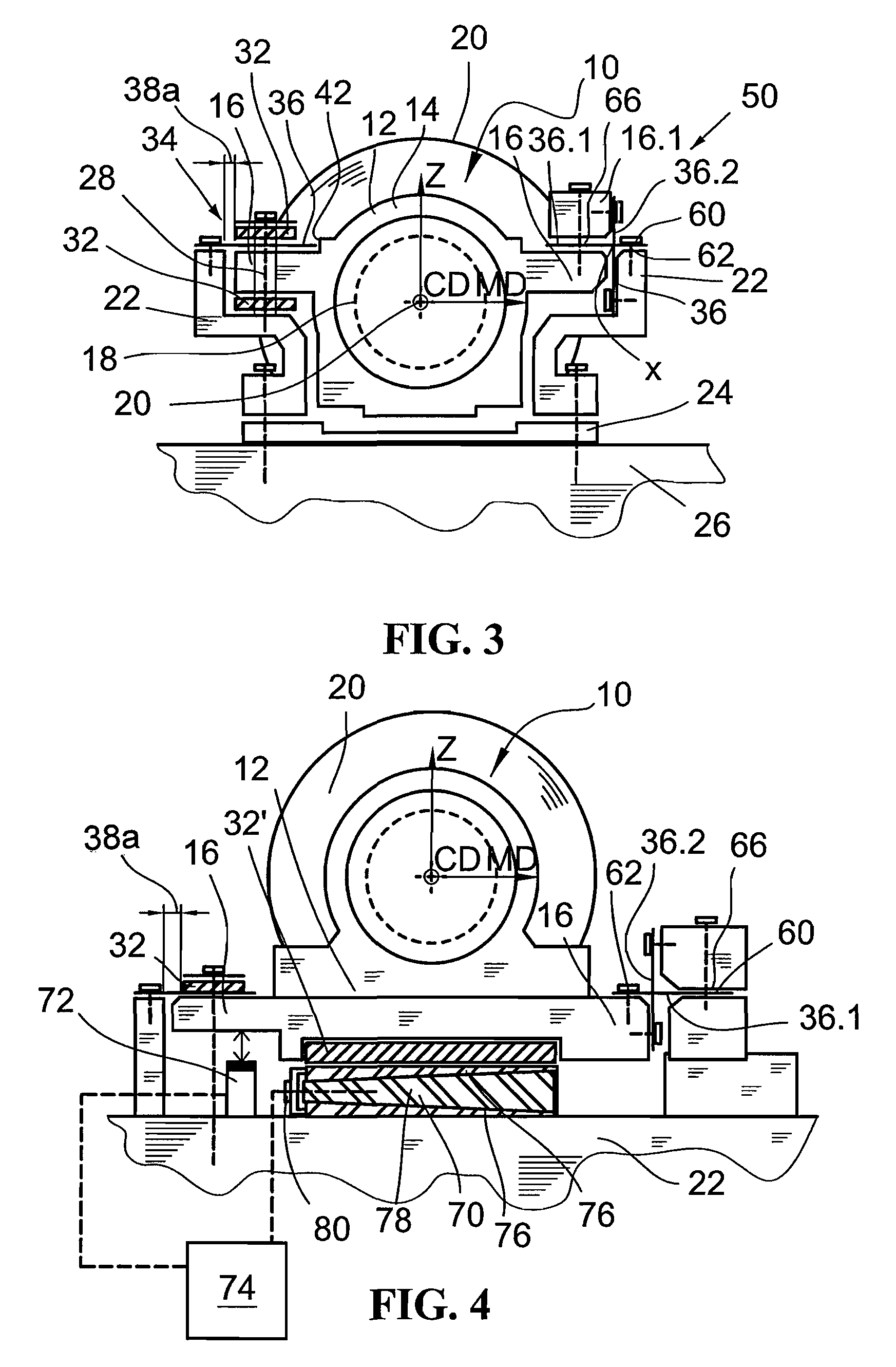
[0029]A support arrangement 10 of a roll of a fibrous-web machine according to an advantageous embodiment of the invention shown in connection with FIG. 1 comprises a first frame part 12 and a second frame part 22. Here, the first frame part 12 consists of a bea...


PUM

PropertyMeasurementUnit
lengthaaaaaaaaaa
thicknessaaaaaaaaaa
thicknessaaaaaaaaaa

Abstract

A support arrangement (10) of a roll of a fibrous-web machine, has a first frame part (12) in which the roll (20) of the fibrous-web machine is supportable from its end when in use and a second frame part (22) in which the first frame part (12) is fastened by means of an elastic fastening. The arrangement has a motion direction control arrangement (34) for controlling the direction of the motion allowed by the elastic fastening in a way determined by the direction control arrangement (34).

Description

CROSS REFERENCES TO RELATED APPLICATIONS[0001]This application claims priority on Finnish Application No. FI 20075476, Filed Jun. 21, 2007, the disclosure of which is incorporated by reference herein.STATEMENT AS TO RIGHTS TO INVENTIONS MADE UNDER FEDERALLY SPONSORED RESEARCH AND DEVELOPMENT[0002]Not applicable.BACKGROUND OF THE INVENTION[0003]The present invention relates to a support arrangement of a roll in a fibrous-web machine. The invention generally relates to supporting a bearing of a roll of a fibrous-web machine or an equivalent shaft to the frame structure. Particularly, the invention relates to a roll of a device or a section of a paper or board machine and supporting its bearing to the frame structure when external force applies to the roll. Such external force can be caused e.g. by another roll, a support fabric or a web reel.[0004]The vibration of rolls is a great problem with present-day fibrous-web machines, inter alia, due to the increase in operating speed. Tradit...

Claims


Application Information

Patent Timeline
Patent Type & Authority Patents(United States)
IPC IPC(8): B21B31/07
CPCB65H18/02D21G1/008B65H18/22B65H2402/521B65H2601/125B65H2301/41486B65H2601/524B65H2402/52D21G1/0226F16C13/02
Inventor T
Owner VALMET TECH INC
Why Eureka
Try Eureka