Tool receptacle with damping element

a technology of damping element and tool receptacle, which is applied in the direction of tool workpiece connection, mechanical apparatus, manufacturing tools, etc., can solve the problems of negative influence on the tool-life of tools and insufficient effectiveness for various applications

Inactive Publication Date: 2019-08-13
OTTO BILZ WERKZEUGFAB
View PDF36 Cites 3 Cited by
  • Summary
  • Abstract
  • Description
  • Claims
  • Application Information

AI Technical Summary

Benefits of technology

[0019]This allows for an effective dampening of vibrations by means of the damping element.
[0066]Both materials allow for a high stiffness so that the tool receptacle can transmit sufficiently high torques without the damping element being too yielding. At the same time these materials have a high temperature resistance allowing also a utilization with a thermal shrink-fit chuck without the danger of a thermal overload of the damping element by means of the shrink-fit process.

Problems solved by technology

When driving tool receptacles rotatingly a high rpms, such as with milling tools or boring tools, frequently oscillations result which may be detrimental to the work result and which also may influence the tool-life of the tools negatively.
Although the known solutions may effect a certain vibration dampening in one or another kind, however, they are not sufficiently effective for various applications.

Method used


Image

  • Tool receptacle with damping element
  • Tool receptacle with damping element
  • Tool receptacle with damping element

Examples


Embodiment Construction

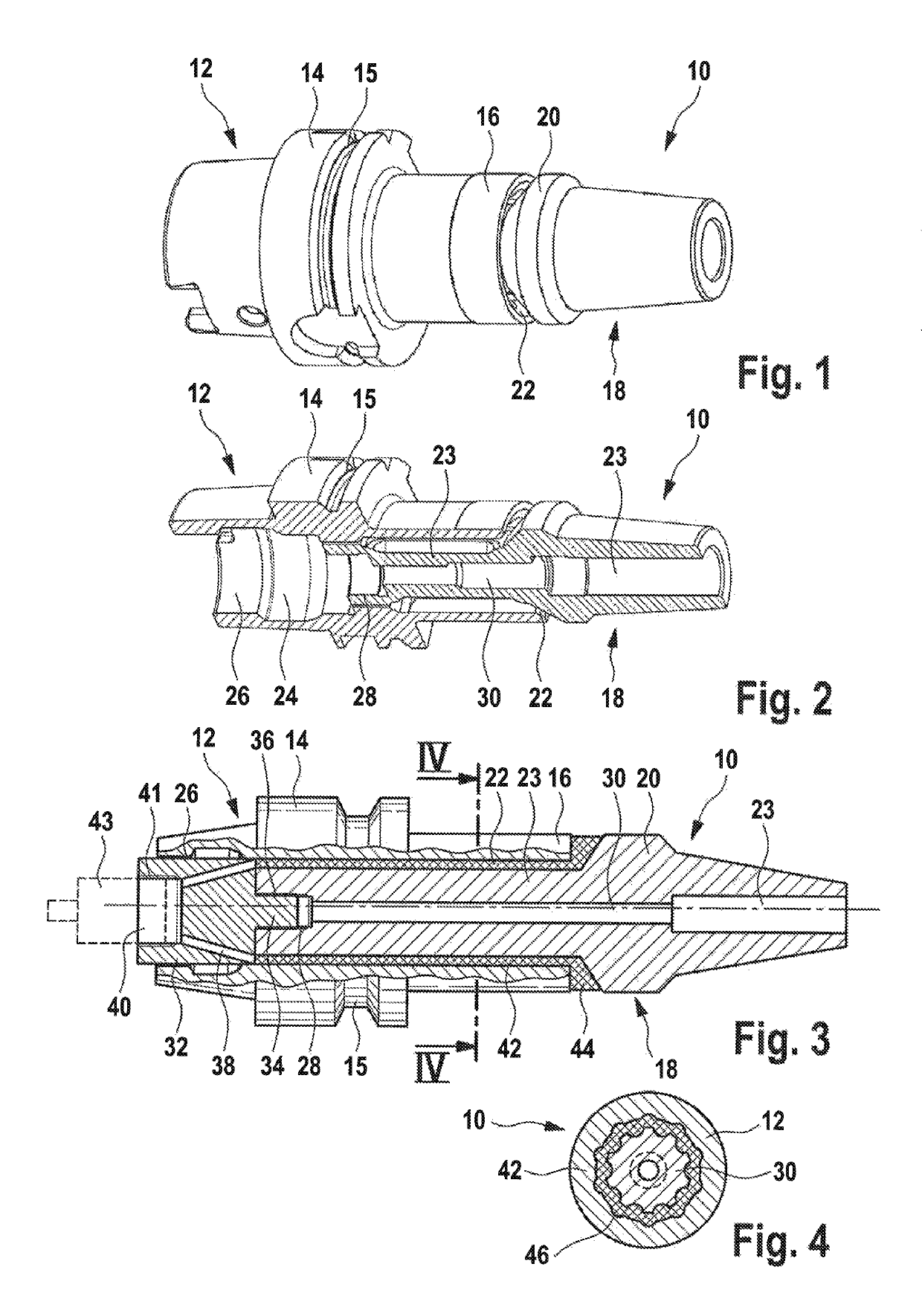
[0082]In FIGS. 1 and 2 a tool receptacle according to the invention is shown in perspective or sectioned, respectively, and designated in total with numeral 10.

[0083]The tool receptacle 10 comprises a base body 12 in the known embodiment of the type HSK comprising a base body 12 for receiving a machine spindle, whereon a flange 14 including an annular groove 15 for handling by means of a tool changer or similar is provided.

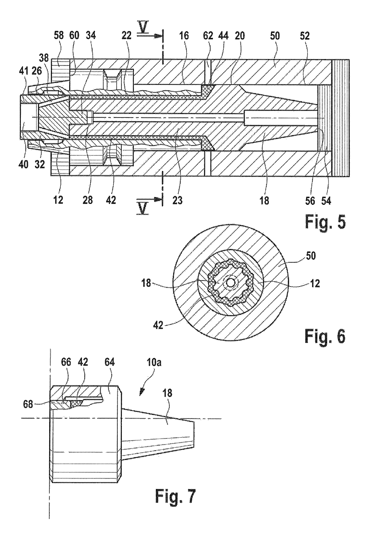
[0084]In addition the tool receptacle 10 comprises a clamping chuck 18 configured as a thermal shrink-fit chuck, shown in FIGS. 1 and 2 with a gap 22 between the base body 12 and the clamping chuck 18 which later is filled by an elastic damping element. In FIGS. 1 and 2 the base body 12 and the clamping chuck 18 are depicted in their reference position with respect to each other, wherein a representation of the damping element filling the gap 22 between the base body 12 and the clamping chuck 18 was dispensed with.

[0085]The clamping chuck 18 comprises a holding se...


PUM

PropertyMeasurementUnit
temperatureaaaaaaaaaa
pressureaaaaaaaaaa

Abstract

A tool holder is provided comprising a base body for coupling with a drive spindle that can be driven rotatingly, whereon a clamping chuck for clamping a tool is provided, further comprising a damping element arranged between the base body and the clamping chuck, wherein the damping element is made of an elastomeric material or of a shape memory alloy, and wherein the clamping chuck is solely connected to the base body by means of the damping element.

Description

CROSS-REFERENCE TO RELATED APPLICATIONS[0001]This application is a continuation of international patent application PCT / EP2015 / 074580, filed on Oct. 23, 2015 designating the U.S.A., which international patent application has been published in German language and claims priority from German utility model application 20 2014 105 440.5, filed on Nov. 12, 2014. The entire contents of these applications are incorporated herein by reference.BACKGROUND OF THE INVENTION[0002]The invention relates to a tool receptacle comprising a base body for coupling with a rotatingly driven drive spindle whereon a clamping chuck for clamping a tool is received, further comprising a damping element between the base body and the clamping chuck being made of a material having a modulus of elasticity being different from the modulus of elasticity of the material whereof the clamping chuck is made, by an amount of at least 50%.[0003]The invention further relates to a device and a method for producing such a t...

Claims


Application Information

Patent Timeline
Patent Type & Authority Patents(United States)
IPC IPC(8): B23B31/02B23B31/117B23B27/00B23B31/08
CPCB23B31/1179B23B31/02Y10T409/304312B23B27/002B23B31/08B23B2226/33B23B2228/16B23B2231/24B23B2240/24B23B2250/12B23B2250/16B23B2270/06Y10T279/17111Y10T279/17965Y10T408/76B23B31/0261
Inventor FRONIUS, JUERGENMANDARELLO, ATTILIOSCHNEIDER, WERNER
Owner OTTO BILZ WERKZEUGFAB
Why Eureka
Try Eureka