Centrifugal compressor
a centrifugal compressor and compressor technology, applied in the direction of machines/engines, stators, liquid fuel engines, etc., can solve the problems of low reliability for stable operation, inability to achieve significant improvement, economic inefficiency, etc., and achieve high reliability and wide operating range.
- Summary
- Abstract
- Description
- Claims
- Application Information
AI Technical Summary
Benefits of technology
Problems solved by technology
Method used
Image
Examples
first embodiment
[0056]Referring now to the drawings, a first embodiment of the invention will be described.
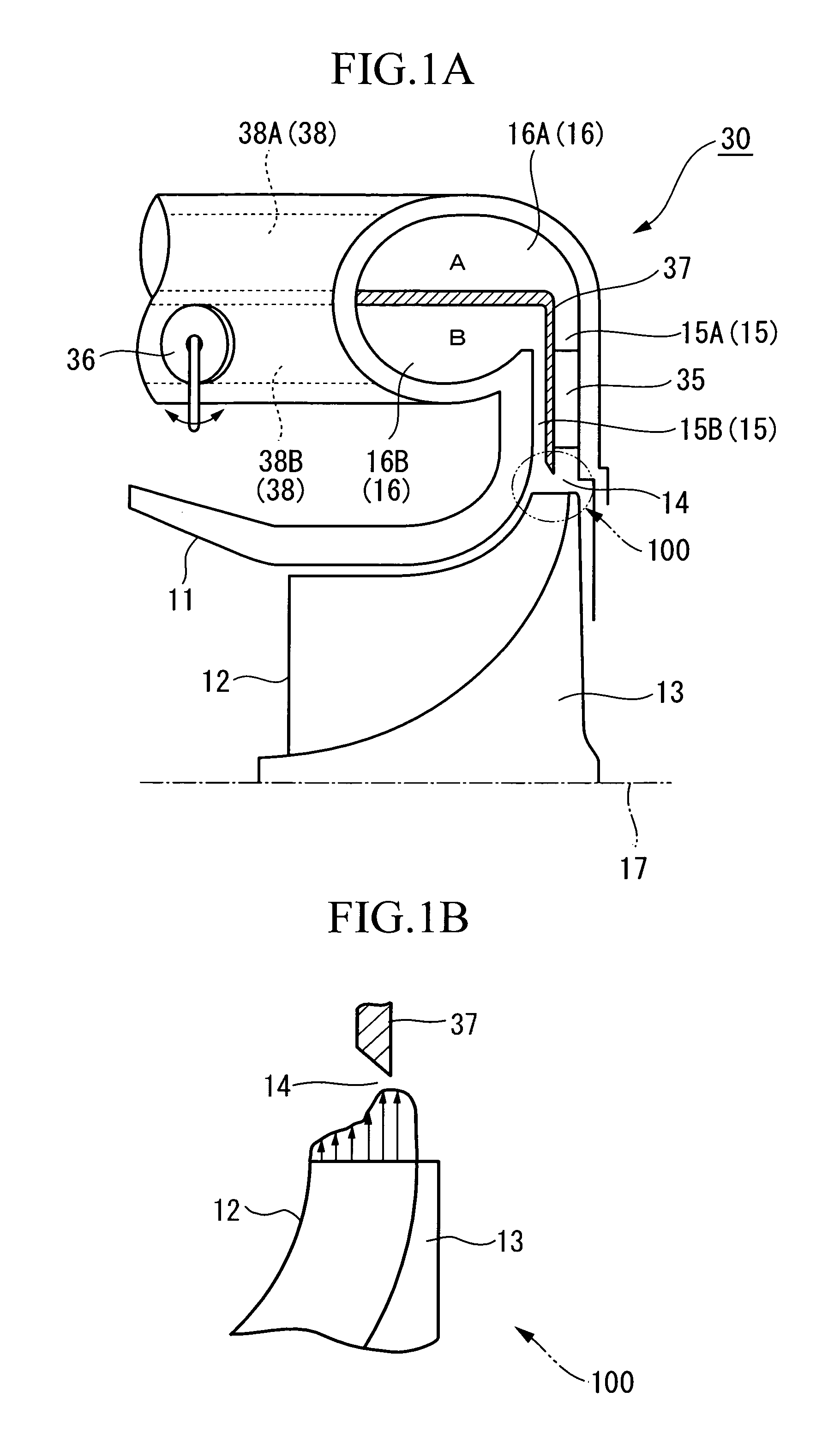
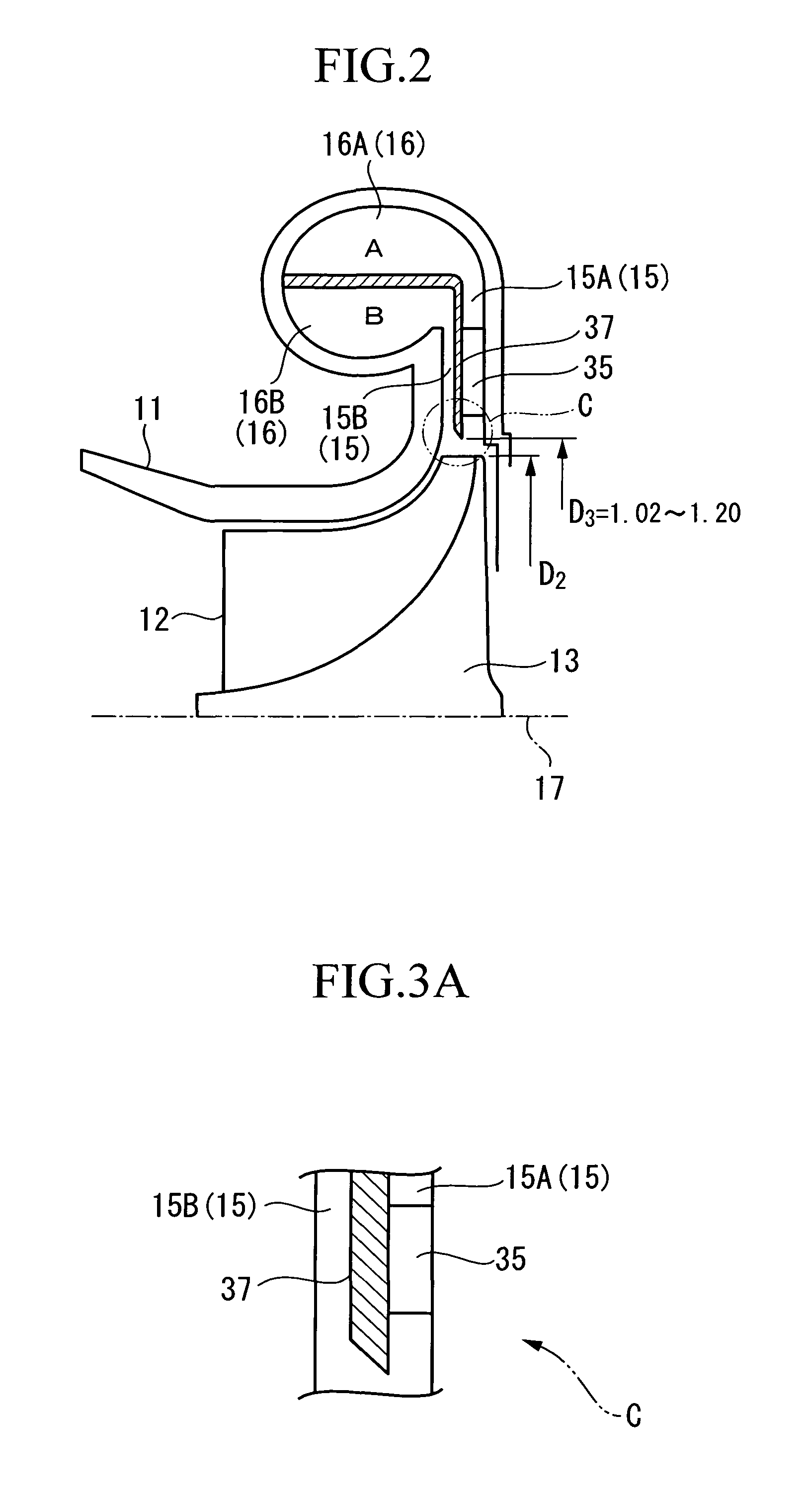
[0057]FIG. 1A shows a vertical cross-sectional view of a centrifugal compressor 30 according to the first embodiment. FIG. 1B shows a flow velocity distribution at the time of discharge from an impeller.
[0058]In FIG. 1A, the centrifugal compressor 30 includes an impeller 13 having a plurality of blades 12 and a casing 11 for housing the impeller 13.
[0059]The impeller 13 is rotated about an axis of rotation 17 by a drive assembly such as a motor or a turbine, not shown. The impeller 13 includes a diffuser section 15 and a volute section 16 on the discharge side of the impeller 13 provided continuously.
[0060]The diffuser section 15 reduces the velocity of air flow discharged from the outer peripheral end of the impeller 13 which rotates in the casing 11 and recovers a static pressure.
[0061]The volute section 16 is connected to the diffuser section 15 on the downstream side and is provided with a...
second embodiment
[0084]Referring now to FIG. 7, a second embodiment of the invention will be described.
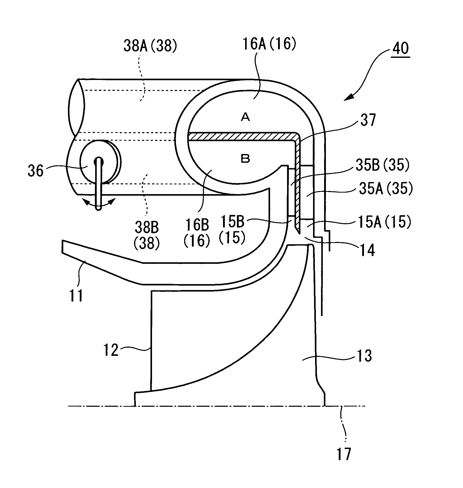
[0085]A centrifugal compressor in the second embodiment is different from that in the first embodiment in that the vanes are provided both on the hub-side diffuser section 15A and the shroud-side diffuser section 15B. The centrifugal compressor in the second embodiment will be described mainly on the different point from the first embodiment, while omitting description of the points which are common to the first embodiment.
[0086]As shown in FIG. 7, the hub-side diffuser section 15A and the shroud-side diffuser section 15B are provided with the vanes 35. The vanes 35 are arranged circumferentially at predetermined distances and are fixed to the casing 11.
[0087]The number of vanes 35A installed on the hub-side diffuser section 15A is larger than the number of vanes 35B installed on the shroud-side diffuser section 15B. Accordingly, the cross-sectional area of the flow channel of the hub-side diffuser...
third embodiment
[0096]Referring now to FIG. 10, a third embodiment of the invention will be described.
[0097]A centrifugal compressor in the third embodiment is different from that in the embodiments shown above in that the vane is provided neither on the hub-side diffuser section 15A nor the shroud-side diffuser section 15B. The centrifugal compressor in the third embodiment will be described mainly on the different point from the embodiments shown above, while omitting description of the points which are common to the embodiments shown above.
[0098]As shown in FIG. 10, the hub-side diffuser section 15A and the shroud-side diffuser section 15B are not provided with the vane. The cross-sectional area of the flow channel of the hub-side diffuser section 15A is set to be smaller than the cross-sectional area of the flow channel of the shroud-side diffuser section 15B.
[0099]The flow rate adjusting valve (flow rate adjuster) 36 for adjusting the flow rates in the respective flow channels is provided in t...
PUM
 Abstract
Description
Claims
Application Information
 - R&D
- Intellectual Property
- Life Sciences
- Materials
- Tech Scout
- Unparalleled Data Quality
- Higher Quality Content
- 60% Fewer Hallucinations
Browse by: Latest US Patents, China's latest patents, Technical Efficacy Thesaurus, Application Domain, Technology Topic, Popular Technical Reports.
© 2025 PatSnap. All rights reserved.Legal|Privacy policy|Modern Slavery Act Transparency Statement|Sitemap|About US| Contact US: help@patsnap.com


