
Endoscope insertion support tool and endoscope device

a technology of endoscope and support tool, which is applied in the field of endoscope insertion support tool and endoscope device, can solve the problems of long inspection time, difficult insertion work and difficulty in smoothly performing the insertion, and achieve the effect of smooth insertion of the insertion section

Active Publication Date: 2012-04-03
OLYMPUS CORP
View PDF19 Cites 5 Cited by
  • Summary
  • Abstract
  • Description
  • Claims
  • Application Information

AI Technical Summary

Benefits of technology

[0014]With the configuration described above, the balloon member is moved between a projection from the distal end of the insertion section and an outer surface of the insertion section by operation for advancing and retracting the advancing and retracting member. The balloon member is inflated and deflated by supply and discharge of the fluid. This makes it easy to smoothly insert the insertion section of the endoscope to a depth side in a tube cavity.
[0016]With the configuration described above, it is easily to smoothly insert the insertion section of the endoscope to a depth side in a tube cavity.

Problems solved by technology

However, in such a push-in method, when the insertion portion is inserted into a large intestine or a small intestine per anus or per os, it may be difficult to smoothly perform the insertion as described below.
When the insertion section is inserted into the depth, in particular, an inspection time is long and insertion work of the insertion section is difficult.
It is extremely difficult to move the endoscope forward into the depth of the intestinal tract.
In the endoscope in the second prior example, since an advancing and retraction amount of the balloon depends on a size of an opening hole opened on the outside of the endoscope tube, a movement amount of the balloon for moving the endoscope forward is limited.
Therefore, it takes time to insert the endoscope.
Thus, it is impossible to grasp the bent intestinal tract, remove the bend, and check a state of the intestinal tract in inserting the endoscope in the visual field direction.
Since it is impossible to check the state of the intestinal tract in this way, it is difficult to smoothly insert the endoscope into the depth of the intestinal tract.

Method used


Image

  • Endoscope insertion support tool and endoscope device
  • Endoscope insertion support tool and endoscope device
  • Endoscope insertion support tool and endoscope device

Examples


first embodiment

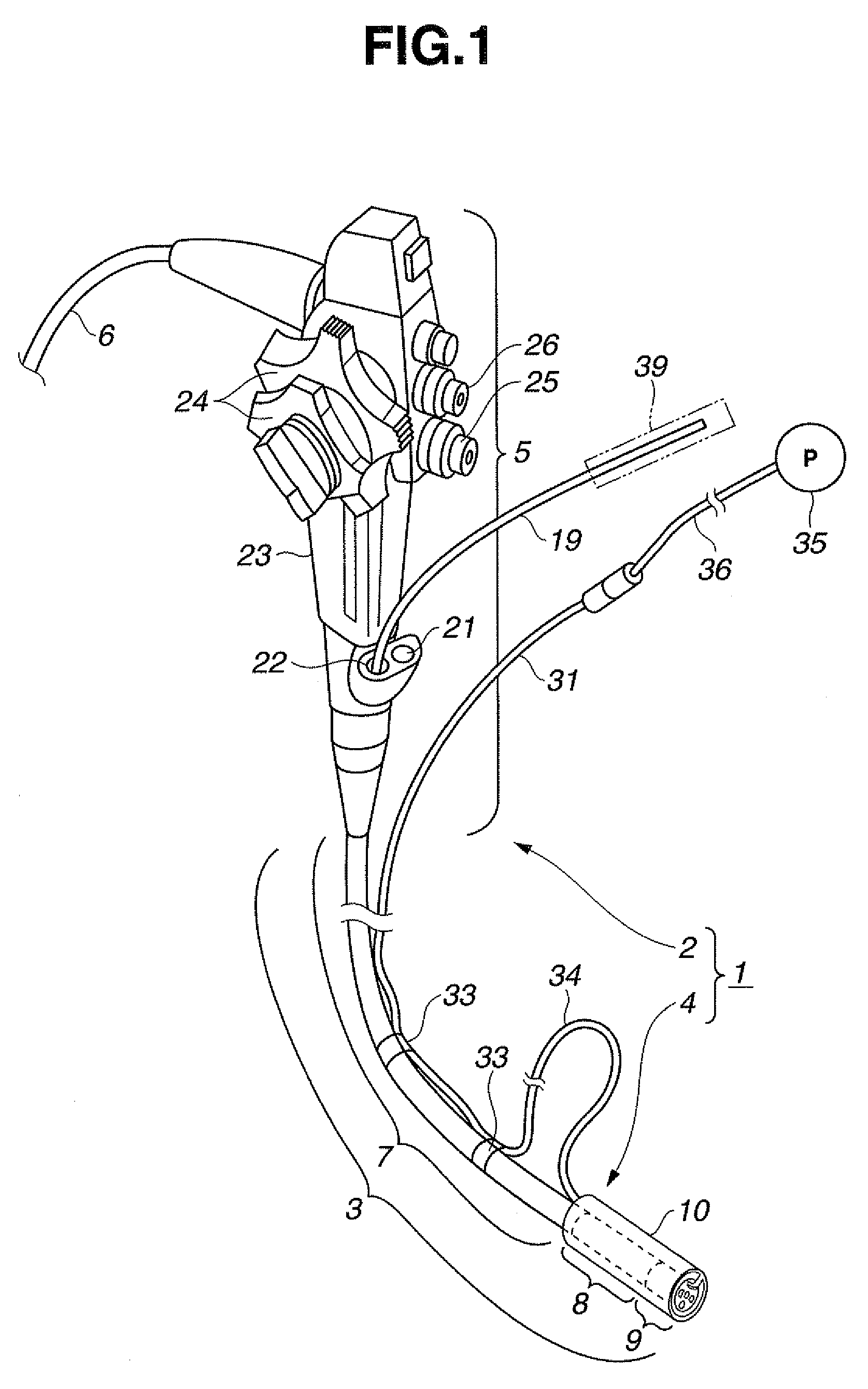
[0038]A first embodiment of the present invention is explained with reference to FIGS. 1 to 10.

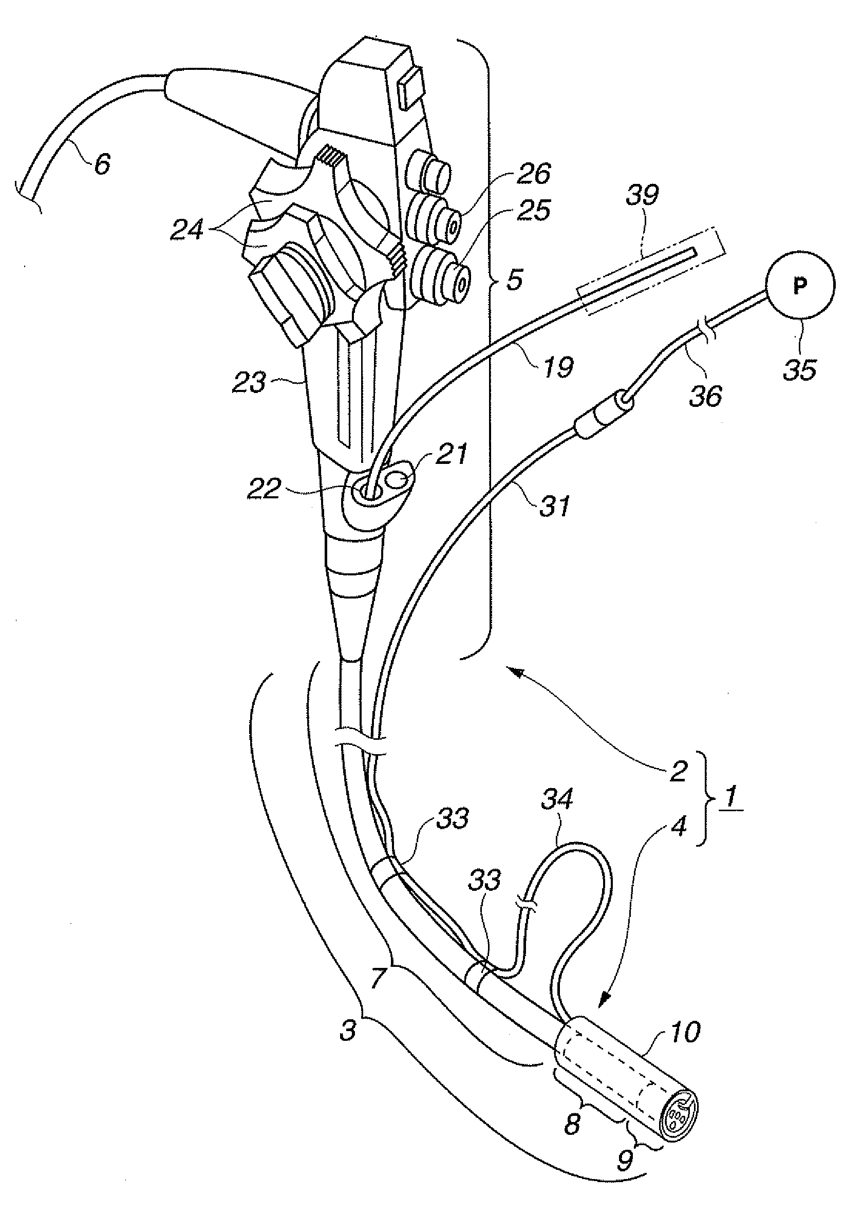
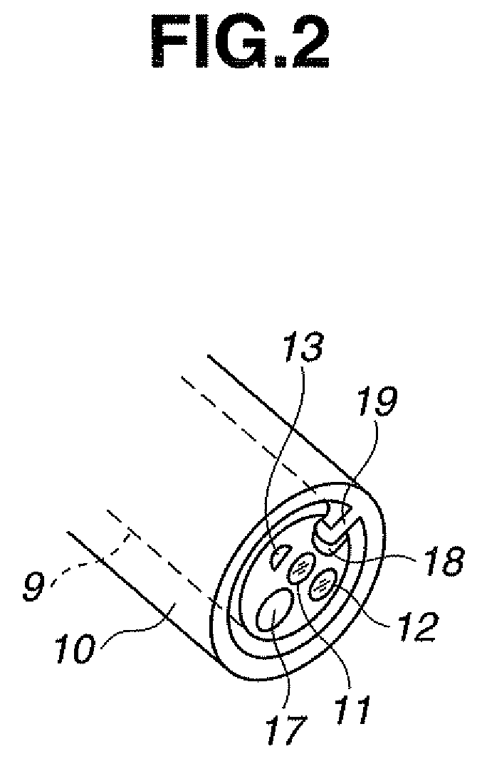
[0039]As shown in FIG. 1, an endoscope device 1 according to the first embodiment of the present invention includes an endoscope 2 used for an endoscope inspection and an endoscope insertion support tool 4 that is detachably attached to a distal end side of an insertion section 3 of the endoscope 2 and supports insertion of the endoscope 2.

[0040]The endoscope 2 has a slim insertion section 3 that is inserted into a body cavity, an operation section 5 that is provided at a proximal end of the insertion section 3, and a universal cable 6 that is extended from a side of the operation section 5. A not-shown connector is provided at an end of the universal cable 6. The connector is detachably connected to a light source device and a signal processing device.

[0041]The insertion section 3 has a slim flexible tube portion 7 having flexibility, a bendable bending portion 8 that is coupled to a dist...

second embodiment

[0118]A second embodiment of the present invention is explained with reference to FIGS. 11 and 12. FIG. 11 shows an endoscope device 1B including the second embodiment of the present invention.

[0119]The endoscope device 1B includes the endoscope 2 same as that in the case of the first embodiment and an endoscope insertion support tool 4B according to the second embodiment.

[0120]In the endoscope insertion support tool 4B according to the present embodiment, the fluid tube 31 shown in FIG. 1 is not provided and, instead, a fluid supplying conduit 44 is formed in the shaft 19. In other words, the shaft 19 is configured by a hollow body. The rear end of the shaft 19 pulled out from the second channel insertion port 22 to the outside is hermetically connected to a connecting portion at a rear end of the tube 36 connected to the balloon control pump 35.

[0121]The operator can freely inflate and deflate the balloon 10 by turning on and off a not-shown balloon control switch.

[0122]Since the ...

third embodiment

[0132]A third embodiment of the present invention is explained with reference to FIG. 14. FIG. 14 shows an endoscope device 1D including the third embodiment of the present invention in a state of use thereof.

[0133]In the endoscope device 1D, the shaft 19 further pulled out from the second channel insertion port 22 to the outside in the endoscope 1B according to the second embodiment is attached to, for example, the second channel insertion port 22, inserted through a rotating device 61 that rotates the shaft 19, and, then, connected to the balloon control pump 35 shown in FIG. 11 via the connecting portion. In FIG. 14, a balloon peripheral portion side is denoted by reference sign 4B because the balloon peripheral portion side has a configuration same as that of, for example, the second embodiment.

[0134]The rotating device 61 is extended to the outside, for example, in a state in which the shaft 19 is attached to a hollow portion of a motor 63 provided in a cylinder 62 grasped by t...


PUM


Abstract

An endoscope insertion support tool includes an advancing and retracting member that is disposed in an insertion section of an endoscope, capable of advancing and retracting in a hollow passage, a distal end portion of which communicates with the outside, and has length projected from a distal end of the insertion section, a balloon member that includes an attaching portion attachable to an outer surface side of the insertion section of the endoscope and is connected to the distal end of the advancing and retracting member and capable of projecting from the distal end of the insertion section according to an advancing and retracting movement of the advancing and retracting member, and a fluid supplying and discharging unit including a conduit that is connected to the balloon member and inflates and deflates the balloon member according to supply and discharge of a fluid to and from the balloon member.

Description

TECHNICAL FIELD[0001]The present invention relates to an endoscope insertion support tool and an endoscope device suitable for smoothly inserting an insertion section of an endoscope into tube cavities such as a large intestine and a small intestine, for example, per anus or per os.BACKGROUND ART[0002]In general, an endoscope includes an operation section that an operator grasps to perform various kinds of operation and an insertion section. The insertion section includes a flexible portion that is a slim tube extended from the operation section and has flexibility, a bending portion that is continuously provided to a distal end of the flexible portion and is bendable in a left and right or an up and down direction, and a rigid distal end portion that is continuously provided to a distal end of the bending portion. The operator inserts the insertion portion into a body cavity per anus, per os, or per naso, observes and diagnoses a predetermined region, or performs treatment or the l...

Claims


Application Information

Patent Timeline
Patent Type & Authority Patents(United States)
IPC IPC(8): A61B1/00A61F2/958
CPCA61B1/00082A61B1/00101A61B1/00133A61B1/0014A61B1/00154A61B1/01A61M25/04A61M25/10A61B1/005
Inventor YAMAYA, KOJI
Owner OLYMPUS CORP
Learn More