Flame cutting device and method for track beam

A technology for flame cutting and rail beams, which is applied to gas flame welding equipment, welding equipment, metal processing equipment, etc., can solve the problems of high spare parts cost, high labor intensity, and high billet loss, so as to reduce the cost of spare parts and reduce the labor load , the effect of labor reduction

Active Publication Date: 2016-01-20
SHAANXI HUAQIN NEW ENERGY TECH CO LTD
View PDF7 Cites 3 Cited by
  • Summary
  • Abstract
  • Description
  • Claims
  • Application Information

AI Technical Summary

Problems solved by technology

[0007] The purpose of the present invention is to overcome the problems of high cost of spare parts, high labor intensity and high loss of steel billets in the existing rail beam saw blade cutting, and provide a simpler and more economical rail beam cutting method. By improving the automation of the equipment, Reduce the labor load of workers, reduce the consumption of spare parts of cutting equipment and the loss cost of steel billets, and achieve the purpose of reducing production costs

Method used


Image

  • Flame cutting device and method for track beam
  • Flame cutting device and method for track beam
  • Flame cutting device and method for track beam

Examples


Embodiment 1

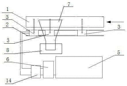
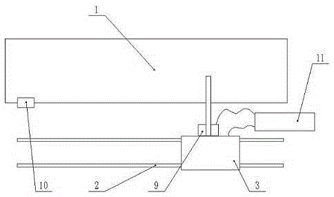
[0038] This embodiment provides a rail beam flame cutting device, such as figure 1 and figure 2 As shown, it includes a mobile cutting trolley system, a gas supply system and a waste recycling device. The mobile cutting trolley system is composed of a trolley track 2 set in front of the rail beam roller table 1 and a trolley 3 on the trolley track 2. Installed on the trolley 3 There is a flame cutting torch 4; the gas supply system includes a gas generator 5 and a safety cabinet 6 connected by stainless steel pipes, and the safety cabinet 6 is connected to the flame cutting torch 4 on the trolley 3 through a hose; the waste recycling device includes an inclined chute 7 and waste Basket 8 and inclined chute 7 are arranged directly below rail beam roller table 1, and waste basket 8 is positioned at the slope end of inclined chute 7 directly below.

[0039] Flame cutting includes flame cutting of other gases including alkanes. The following is an example of oxyhydrogen flame cu...

Embodiment 2

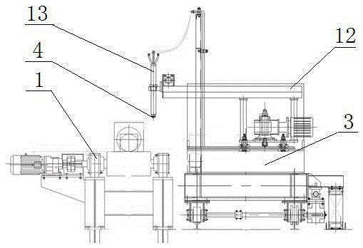
[0044] This embodiment describes the specific structure of the trolley 3 and the specific distribution of the trolley 3 and the rail beam roller table 1, as image 3 , 4 , 5, in this embodiment, the dolly 2 includes wheels, a vehicle frame and a power drive motor on the vehicle frame, and the first telescopic body 12 is also fixed on the vehicle frame, and the first telescopic body 12 is horizontally arranged and perpendicular to In the direction of the roller table of the rail beam roller table 1, the end of the first telescopic body 12 is connected to the second telescopic body 13, and the second telescopic body 13 is vertically arranged and perpendicular to the direction of the roller table of the rail beam roller table 1. The end portions of the two telescopic bodies 13 are equipped with flame cutting torches 4 .

[0045] The movement of the trolley 3 on the trolley track 2 is mainly completed by the power drive motor of the cutting trolley. The flame cutting gun 4 has th...

Embodiment 3

[0053] Inclined chute 7 is the inclined plane that steel plate is laid, and steel plate edge has limit baffle to prevent scrap steel from slipping to both sides; Set with lugs.

[0054] The inclined chute 7 is placed directly below the rail beam track foundation pit, so as to ensure that each cut section can accurately fall in the inclined chute 7 to facilitate recovery. The waste basket 8 is placed on the end of the inclined surface of the inclined chute 7 to ensure that each waste section that slides through the inclined chute 7 can slide into the waste basket 8 . When the volume of the waste basket 8 is fully loaded, the motor is operated to move the waste basket 8 along the pre-laid basket track to the range of row hoisting, and a new waste basket 8 is replaced by hoisting lugs.


PUM


Abstract

The invention discloses a flame cutting device and method for a track beam. According to the flame cutting device and method for the track beam, traditional saw blade cold cutting of the track rail is transformed into flame hot cutting. A hydrogen-oxygen generator (fuel gas generator) generates hydrogen-oxygen mixed gas used for cutting in the gas generation manner that gas is used while generated; the hydrogen-oxygen mixed gas is regulated through a safety device and an energy medium box; meanwhile, an auxiliary is regulated through the energy medium box; the hydrogen-oxygen mixed gas and the auxiliary are conveyed to a cutting gun on a trolley; and then the cutting gun is used for cutting work. According to the flame cutting device and method, the beneficial effects that the cutting section cut by hydrogen-oxygen flames is smooth, slag hanging does not exist, a cutting seam is small, the automation degree is high, and environmental pollution does not exist are utilized, the movable trolley and a waste recovery system which are designed for the track beam are combined, and therefore compared with traditional saw blade cutting, the flame cutting device and method have the beneficial effects of being low in cost, low in labor intensity, good in cutting quality and the like. The labor capacity of workers is reduced by improving the automation degree of the device, spare consumption and loss cost of steel billets of the cutting device are reduced, and the purpose of reducing production cost is achieved.

Description

technical field [0001] The invention relates to a rail beam flame cutting device and a cutting method, and is a rail beam cutting device and method with low cost, high quality and high degree of automation. Background technique [0002] At present, domestic rail and beam manufacturing enterprises generally use traditional saw blades to cut the head, tail and center of the continuous casting slab on the existing roller table. [0003] After long-term production and practical application experience, there are many shortcomings in the practical application of saw blade cutting rail beams: [0004] First of all, it is difficult to cut large-section continuous casting slabs with saw blades, which limits the development of enterprises in large billets; secondly, the loss of saw blades is very serious when cutting with saw blades, and the consumption of spare parts is large, which greatly improves production. Cost; third, the service life of the saw blade is very short, it cannot ...

Claims


Application Information

Patent Timeline
Patent Type & Authority Applications(China)
IPC IPC(8): B23K7/00B23K7/10
CPCB23K7/00B23K7/10B23K7/102Y02P70/10
Inventor 折生阳王彦东杨炎庄新东田涛成雨超
Owner SHAANXI HUAQIN NEW ENERGY TECH CO LTD
Why Eureka
Try Eureka