Method and apparatus for protecting sterile drapes in surgical thermal treatment systems

a technology of thermal treatment system and drape, which is applied in the direction of lighting and heating apparatus, furniture, applications, etc., can solve the problems of compromising the required sterility, complicating the procedure, and glycol or other thermal transfer medium being typically highly flammable, so as to prevent puncture

Active Publication Date: 2012-04-03
PATENTED MEDICAL SOLUTIONS LLC
View PDF155 Cites 22 Cited by
  • Summary
  • Abstract
  • Description
  • Claims
  • Application Information

AI Technical Summary

Benefits of technology

[0011]Accordingly, it is an object of the present invention to prevent puncturing of a surgical drape disposed in a thermal treatment system basin when objects (e.g., medical instruments, containers, etc.) are placed in the basin.
[0012]It is another object of the present invention to prevent puncturing of a surgical drape disposed in a thermal treatment system basin by covering or reinforcing the drape container floor.
[0013]Yet another object of the present invention is to prevent puncturing of a surgical drape disposed in a thermal treatment system basin by covering the drape container floor with a plate or pad to protect the drape.
[0014]A further object of the present invention is to prevent puncturing of a surgical drape disposed in a thermal treatment system basin by employing a thick intermediate drape section disposed within the basin to protect the drape.

Problems solved by technology

Additionally, the glycol or other thermal transfer medium is typically highly flammable or toxic and, in any event, complicates the procedure.
However, during the course of a surgical procedure, objects are often tossed, dropped or not carefully placed in the basin which sometimes causes the surgical drape or sheet to be punctured or torn, thereby compromising the required sterility.
Often it is not until after the surgical procedure has been completed that it becomes evident that sterility has been compromised.
Although some open basin thermal treatment systems and drapes employ a trivet or stand (e.g., U.S. Pat. No. 6,087,636) to elevate objects within the basin above the basin floor, or have been adapted to detect when the cover has been punctured and alert the surgical staff (e.g., U.S. Pat. No. 6,810,881), these systems generally do not shield or reinforce the drape to prevent puncture.

Method used


Image

  • Method and apparatus for protecting sterile drapes in surgical thermal treatment systems
  • Method and apparatus for protecting sterile drapes in surgical thermal treatment systems
  • Method and apparatus for protecting sterile drapes in surgical thermal treatment systems

Examples


Embodiment Construction

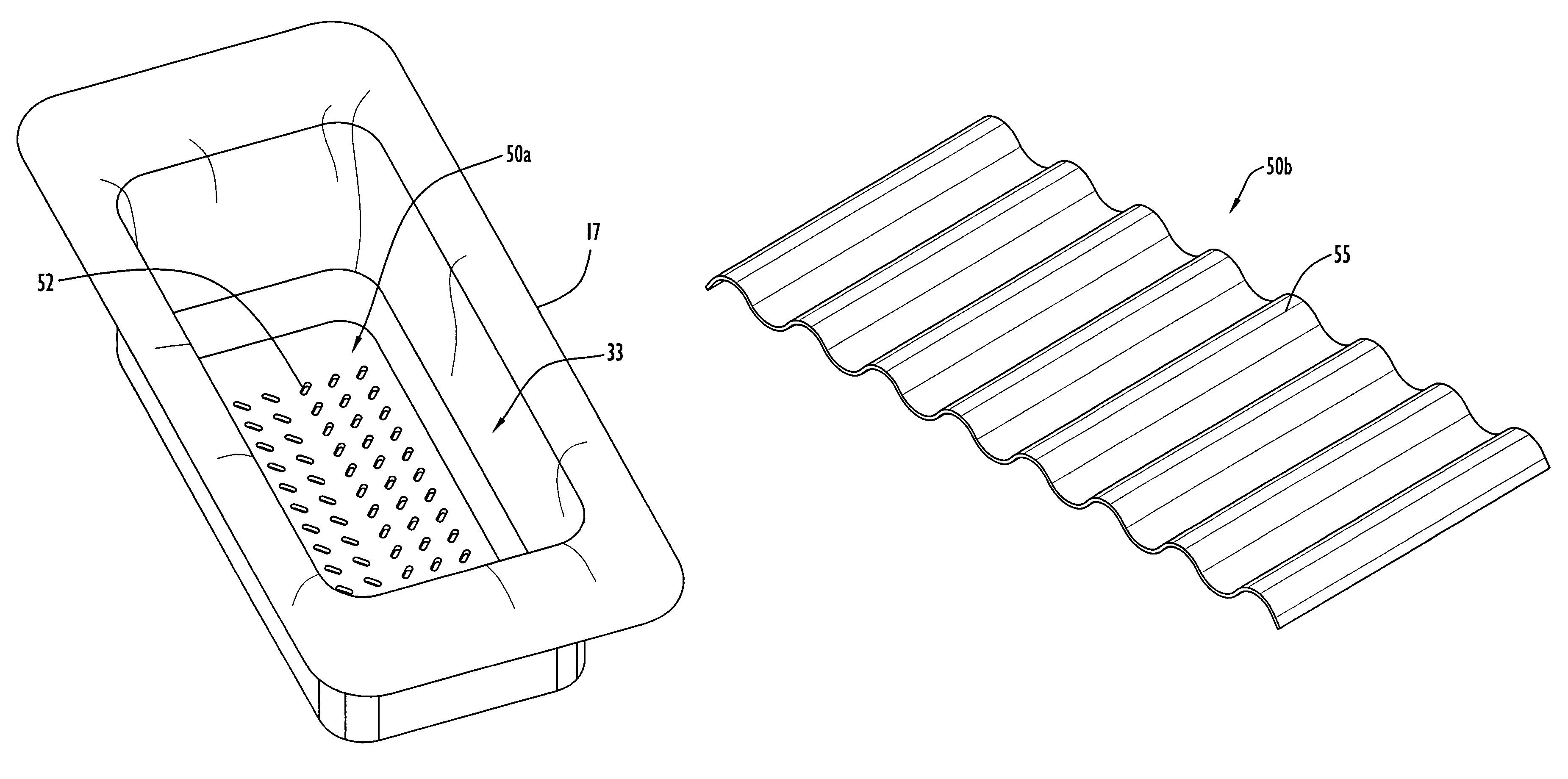
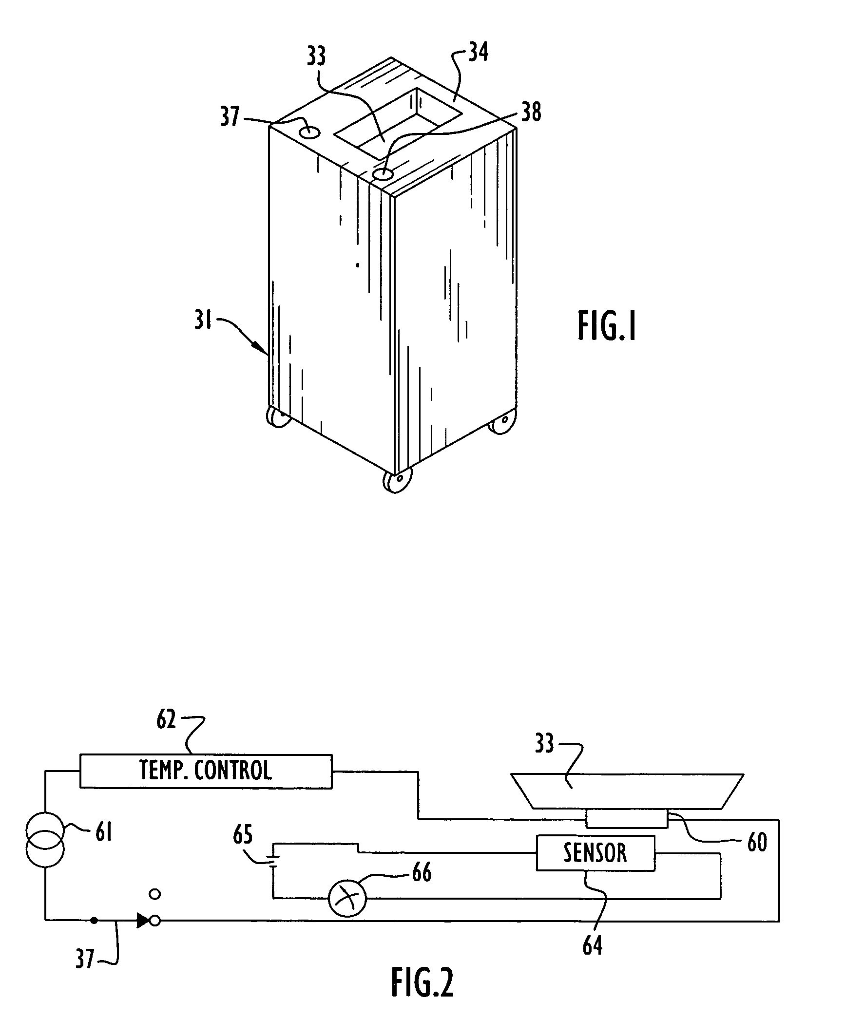
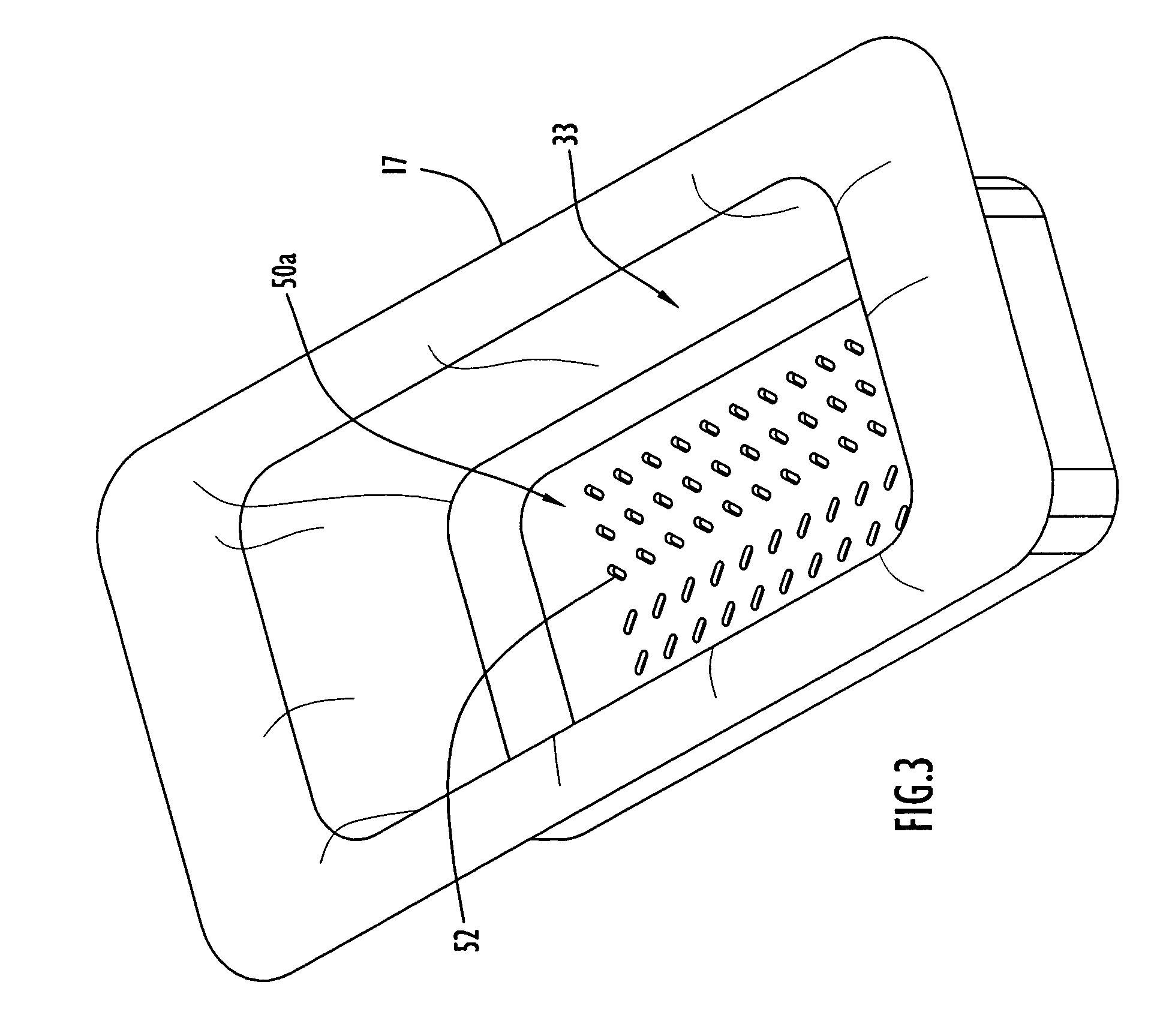
[0029]Referring to FIG. 1 of the accompanying drawings, a typical thermal treatment system for thermally treating a sterile medium (i.e., liquid) employed by the present invention includes a cabinet or housing 31 and a warming basin 33 recessed into the top surface 34 of cabinet 31. Basin 33 may be any shape, however, by way of example only, the basin is illustrated as being substantially rectangular. A heater power switch 37 and a temperature controller / indicator 38 are provided on top surface 34 adjacent the warming basin. It is to be understood that the thermal treatment system described above may have various configurations and include a plurality of basins warming and / or cooling a sterile medium. An example of such a system is disclosed in the aforementioned Faries, Jr. et al. (U.S. Pat. No. 5,333,326) patent.

[0030]The manner of heating sterile liquid in warming basin 33 is illustrated schematically in FIG. 2. Specifically, an electrical circuit includes a power source 61 conne...


PUM


Abstract

Surgical drapes employed with thermal treatment systems are re-enforced according to the present invention. This protects against punctures and tears when objects are placed in a receptacle formed by a drape within a thermal treatment system basin to contain a sterile medium. In one embodiment, a plate or pad is used to protect the drape. The plate or pad may be formed of rigid or flexible material of various configurations. The plate or pad may be solid or perforated (e.g., with holes, slots, mesh, etc.), and may be loosely placed on or fixedly attached to the drape. The plate or pad may have depending feet or protrusions that support the plate spaced above the drape material. Alternatively, the drape may be utilized without the plate and include a thick intermediate section resistant to puncture that is disposed within the thermal treatment system basin.

Description

CROSS-REFERENCE TO RELATED APPLICATIONS[0001]This application claims priority from U.S. Provisional Patent Application Ser. No. 60 / 712,906, entitled “Method and Apparatus For Protecting Sterile Drapes in Surgical Warming Systems” and filed Sep. 1, 2005, the disclosure of which is incorporated herein by reference in its entirety.BACKGROUND OF THE INVENTION[0002]1. Technical Field[0003]The present invention pertains to improvements in methods and apparatus for thermally treating surgically sterile liquid, and in using these types of systems, typically located in a surgical operating room, to thermally treat objects (e.g., sponges, needles, scalpels, endoscopes, containers, etc.) in a sterile manner. In particular, the present invention is an improvement of the methods and apparatus disclosed in U.S. Pat. No. 4,393,659 (Keyes et al.), U.S. Pat. No. 4,934,152 (Templeton), U.S. Pat. No. 5,333,326 (Faries, Jr. et al.), U.S. Pat. No. 5,522,095 (Faries, Jr. et al.), U.S. Pat. No. 6,087,636 ...

Claims


Application Information

Patent Timeline
Patent Type & Authority Patents(United States)
IPC IPC(8): A61B19/00A61F7/00F27D11/00
CPCA61B19/081A61F7/0085A61B46/10
Inventor FARIES, JR., DURWARD I.HEYMANN, BRUCE R.HENDRIX, DAVID
Owner PATENTED MEDICAL SOLUTIONS LLC
Why Eureka
Try Eureka