Drive arrangement

a technology of driving arrangement and drive shaft, which is applied in the direction of mechanical energy handling, dynamo-electric components, synchronous machines, etc., can solve the problem that the motor cannot however satisfactorily execute high-frequency movements

Inactive Publication Date: 2012-04-03
SIEMENS AG
View PDF6 Cites 0 Cited by
  • Summary
  • Abstract
  • Description
  • Claims
  • Application Information

AI Technical Summary

Benefits of technology

[0005]An object of the invention is to specify a drive arrangement by means of which both a low-frequency, uniform movement and also a higher-frequency alternating movement are able to be effectively generated.
[0010]The invention starts from the consideration that the at least two motors which are each designed for a different type of movement can be designed separately without them having a disruptive effect on each other during operation in their respective desired working areas. This results in the need to design the coupling members such that an undesired feedback between the motors is avoided.
[0020]The periodicity of the desired movement pattern makes it possible to exploit resonance characteristics in order to minimize the energy demand of the arrangement. In this case the resonant frequency which is determined by the movement of the system comprising the second motor and the machine component coupled thereto against the first motor corresponds to the basic frequency of the periodic movement pattern. This occurs through a corresponding layout of the first coupling member. In the synchronized state of the arrangement an ongoing conversion process between kinetic and potential energy then occurs, through which the desired alternating movement is maintained. Only the energy losses arising from attenuation and friction must by supplied. This makes the drive arrangement especially energy-efficient.
[0022]As mentioned, resonance effects of the drive arrangement are able to be exploited by means of the suitably-selected first coupling member for energy minimization. The rigid coupling between the second motor and the machine component promotes the quality of the movement which is to be transmitted via the second motor to the coupled machine component.
[0023]In a further advantageous embodiment a resonant frequency of the overall system, comprising the first and the second motor, the first and the second coupling member as well as the machine component coupled to the second motor by means of the second coupling member is tuned to the basic frequency of the desired periodic movement pattern. The first coupling member in this case is a means to make this tuning possible.
[0029]By exploiting resonance effects, whereby the drive dynamics of the drive arrangement are influenced by means of the first coupling member, the energy requirement of the drive arrangement can be minimized.

Problems solved by technology

Such motors cannot however execute high-frequency movements satisfactorily, since the high intrinsic inertia would demand high torques with any dynamic movement conveyed, whereby higher-frequency movements of such motors are only able to be realized with a small amplitude.

Method used


Image

  • Drive arrangement
  • Drive arrangement

Examples


Embodiment Construction

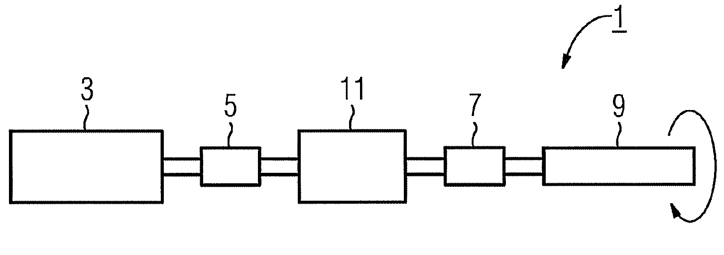
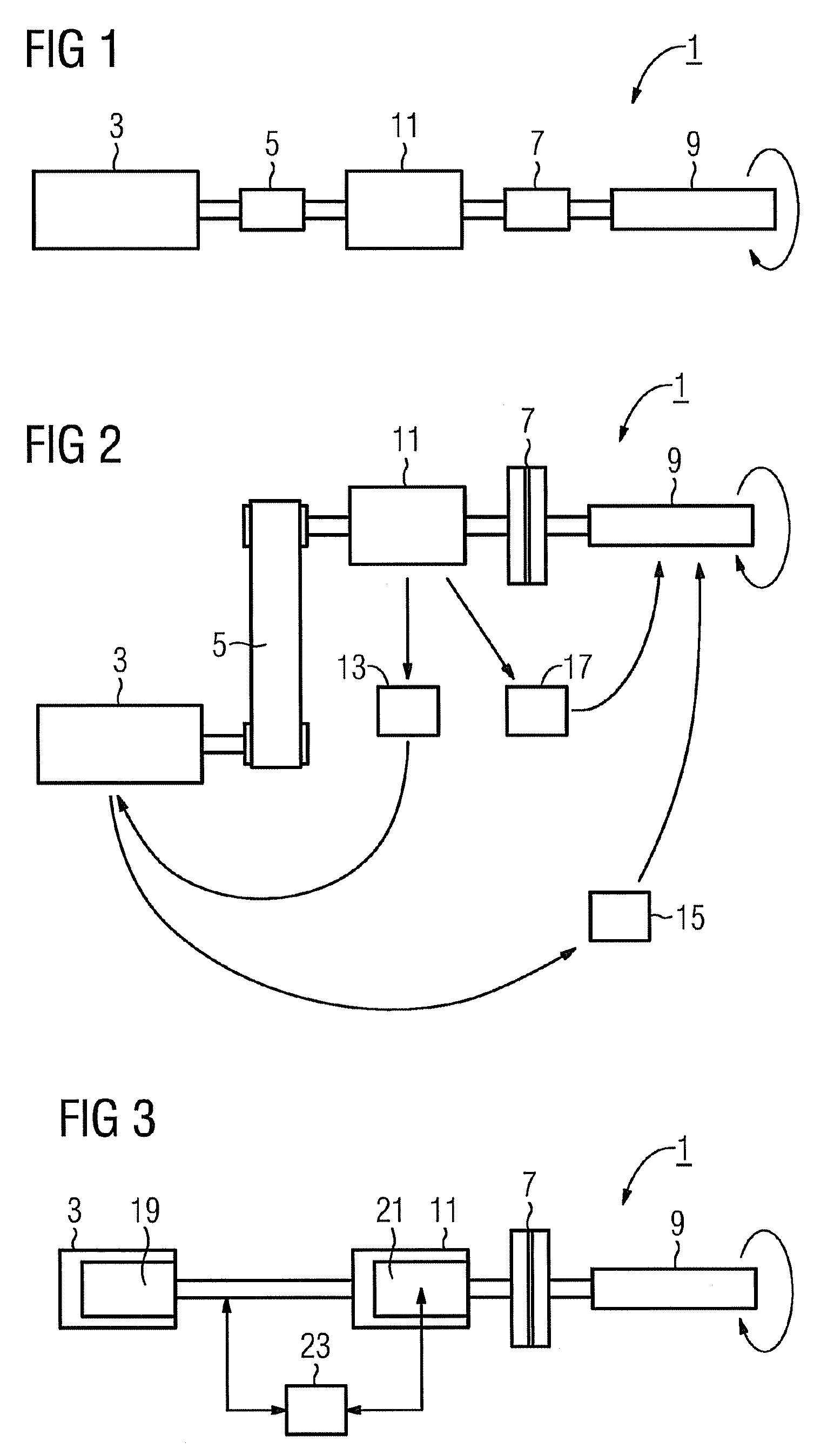
[0036]FIG. 1 shows a schematic diagram of a drive arrangement 1. A machine component 9 is intended in this case to preferably execute rotational movements, whereby a uniform, low-frequency basic load and also a higher-frequency alternating load are to be transmitted to the machine component 9.

[0037]A first motor 3 is provided for realizing the low-frequency uniform movement (basic load). A second motor 11 is available for the high-frequency alternating movement. The drive arrangement comprises the first motor 3, the second motor 11, and also first coupling member 5 for coupling the first 3 motor to the second motor 11 and a second coupling member 7. The second coupling member 7 is intended and implemented for coupling in the machine component 9 and is preferably a rigid coupling to guarantee the quality of the transmission of the basic and alternating movement to the machine component. Via the second motor 11 both the lower-frequency basic movement and also the higher-frequency alte...


PUM

PropertyMeasurementUnit
constant torqueaaaaaaaaaa
dynamic torqueaaaaaaaaaa
constant basic frequencyaaaaaaaaaa

Abstract

A drive arrangement with a first motor and a second motor is described, the first and second motor being coupled via a first coupling unit. The first motor is provided to generate uniform low-frequency movements and the second motor performs a higher frequency alternating movement to be overlapped. The total movement is transmitted from the second motor to a machine component coupled via a second coupling unit. The first coupling unit is configured to transfer the uniform low-frequency movement of the first motor to the second motor, wherein a transmission of the higher frequency alternating movement of the second motor to the first motor is suppressed.

Description

CROSS REFERENCE TO RELATED APPLICATIONS[0001]This application is the US National Stage of International Application No. PCT / EP2007 / 063082 filed Nov. 30, 2007 and claims the benefit thereof. The International Application claims the benefit of German Patent Application No. 10 2006 057 098.7 DE filed Dec. 4, 2006, both of the applications are incorporated by reference herein in their entirety.FIELD OF INVENTION[0002]The invention relates to a drive arrangement comprising at least two motors.BACKGROUND OF INVENTION[0003]A number of technical processes exist in which generation of a movement in a wide frequency range is necessary. In manufacturing there are plastic molding machines for example in which the distanglement method (e.g. for extrusion) is used. In this case the provision of both a uniform basic movement and also a higher-frequency alternating movement is necessary.[0004]Known motors are usually tuned to the movement creation within a specific frequency range. Thus for example...

Claims


Application Information

Patent Timeline
Patent Type & Authority Patents(United States)
IPC IPC(8): H02K7/20B29C48/03
CPCB29C45/5008B29C47/0801B29C47/0805H02K7/10B29C47/0009H02K16/00B29C48/03B29C48/252B29C48/2526
Inventor HAMANN, JENSKREJTSCHI, JURGENSCHAFERS, ELMAR
Owner SIEMENS AG
Why Eureka
Try Eureka