Apparatus and method for vaporizing a liquid fuel

a liquid fuel and apparatus technology, applied in the field of oxidation reactors, can solve the problems of increasing weight and parasitic power requirements, nozzles tend to be coke-like at high operating temperature, and high-pressure electromagnetic injectors are incapable of operating with heavy fuels in combustors and reformers of compact and portable, etc., to achieve the effect of maintaining steady-state operation and minimizing parasitic energy demand

Active Publication Date: 2016-06-21
PRECISION COMBUSTION
View PDF45 Cites 0 Cited by
  • Summary
  • Abstract
  • Description
  • Claims
  • Application Information

AI Technical Summary

Benefits of technology

[0042]The novel method and apparatus of this invention find advantageous use in vaporizing and, optionally, igniting a liquid fuel, preferably a distillate fuel, including logistics fuels, such as JP-8 fuel. In contrast to prior art methods that use air-assisted high pressure electromagnetic nozzles to vaporize liquid fuels, the novel method and apparatus of this invention employ a low pressure design requiring less than about 0.75 kPa of air or fuel pressure (less than 3 inches water at 4° C.). The apparatus can also maintain steady-state operation using recuperated oxidant or burner air. In contrast to prior art electrostatic atomization methods, neither fuel additives nor high voltage is required of the present invention. Moreover, the vaporizer of this invention is particularly adaptable to micro-burner markets where fuel flow rates below about 100 cm3 / hr and low pressure drop are needed.
[0043]The apparatus and method of this invention can be more advantageously adapted for use with a hybrid burner, which operates in flame or catalytic mode or simultaneously in both flame and catalytic modes as described in detail hereinafter. The hybrid burner is even more advantageous in facilitating rapid cold start-up wherein catalyst and incoming flows of fuel and oxidant are fed to the burner at ambient temperature, taken as a range from about −30° C. to about 35° C. Rapid cold start-up is preferably represented by heating from ambient temperature to flame operation in less than 1.3 minutes. Advantageously, facile start-up from ambient conditions minimizes parasitic energy demand required from a battery, which may be on-board and required to start the burner and any associated engine. Even more advantageously, the apparatus and method of this invention after start-up provide for efficient fuel combustion or reforming in flameless catalytic mode. The apparatus and process of this invention are most advantageously adapted for compact and portable burners and reformers having a fuel input of less than about 5 kWth.

Problems solved by technology

Moreover, at such low flow rates, the nozzle tends at high operating temperature to coke due to clogging of its flow path and / or orifice from fuel breakdown or coking.
High-pressure electromagnetic injectors are incapable of operating with heavy fuels in combustors and reformers of compact and portable size for a time frame of 100 hours; let alone for the more than 1,000 hours that might be preferred for logistics operations.
Moreover, high pressure electromagnetic injectors typically require air compression, which increases weight and parasitic power requirements and decreases efficiency and portability in a stand-alone system.
Other means of vaporizing a liquid fuel are known, but they too are not suitable for use with distillate fuels in logistics operations.
Conventional electrostatic atomization for vaporizing a liquid fuel has the advantages of large fuel passages and acceptable function, but disadvantageously requires high voltage.
Also, electrostatic atomization disadvantageously requires conductivity-enhancing chemical additives in the fuel and runs the risk of fuel ignition from electrical charge build-up during transient operation.
Ultrasonic vaporization and piezoelectric vaporization are less conventional methods that are disadvantageously costly and undependable.

Method used


Image

  • Apparatus and method for vaporizing a liquid fuel
  • Apparatus and method for vaporizing a liquid fuel
  • Apparatus and method for vaporizing a liquid fuel

Examples


example

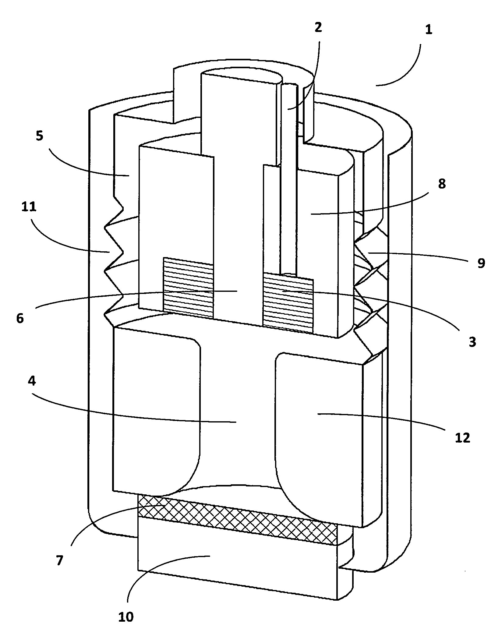
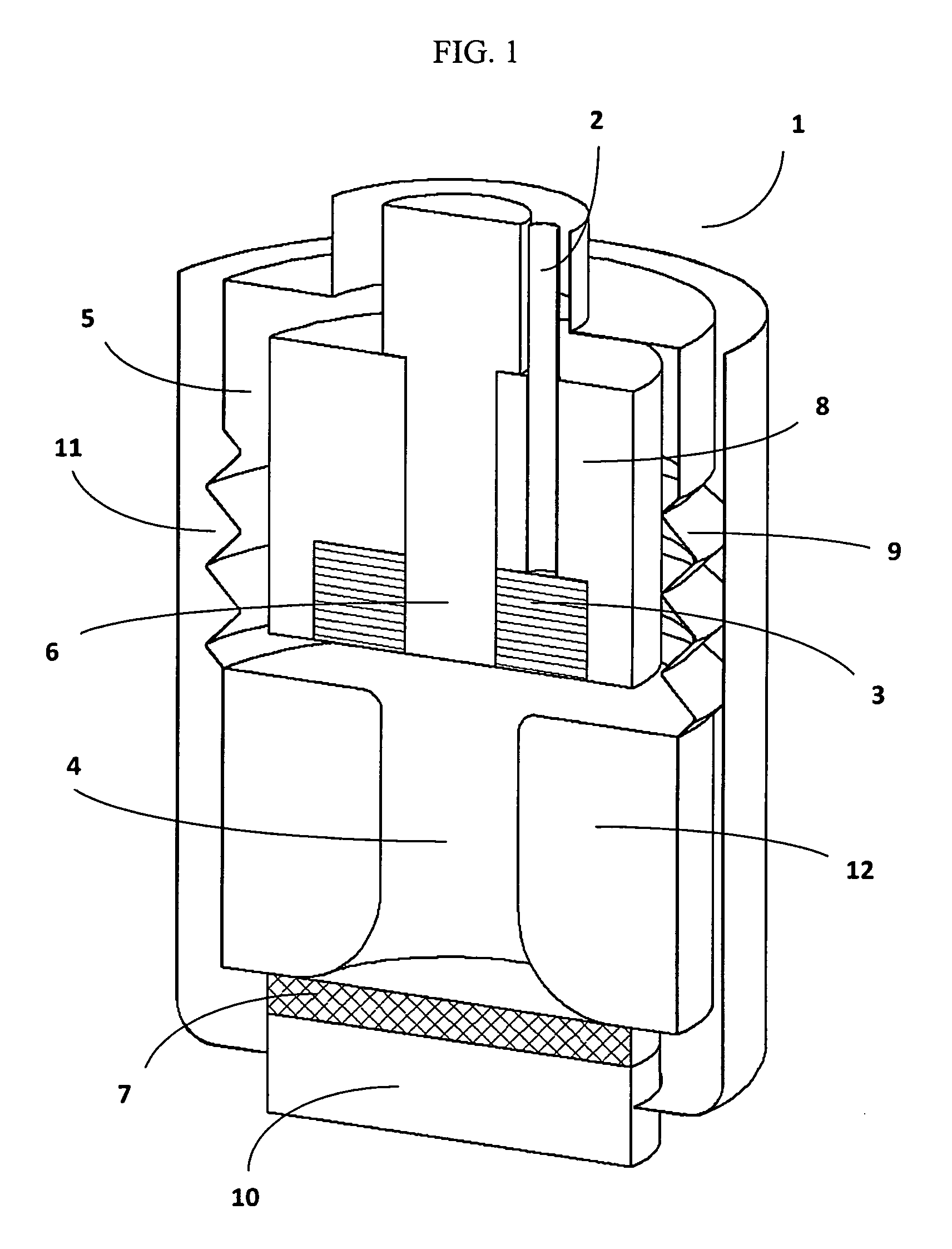
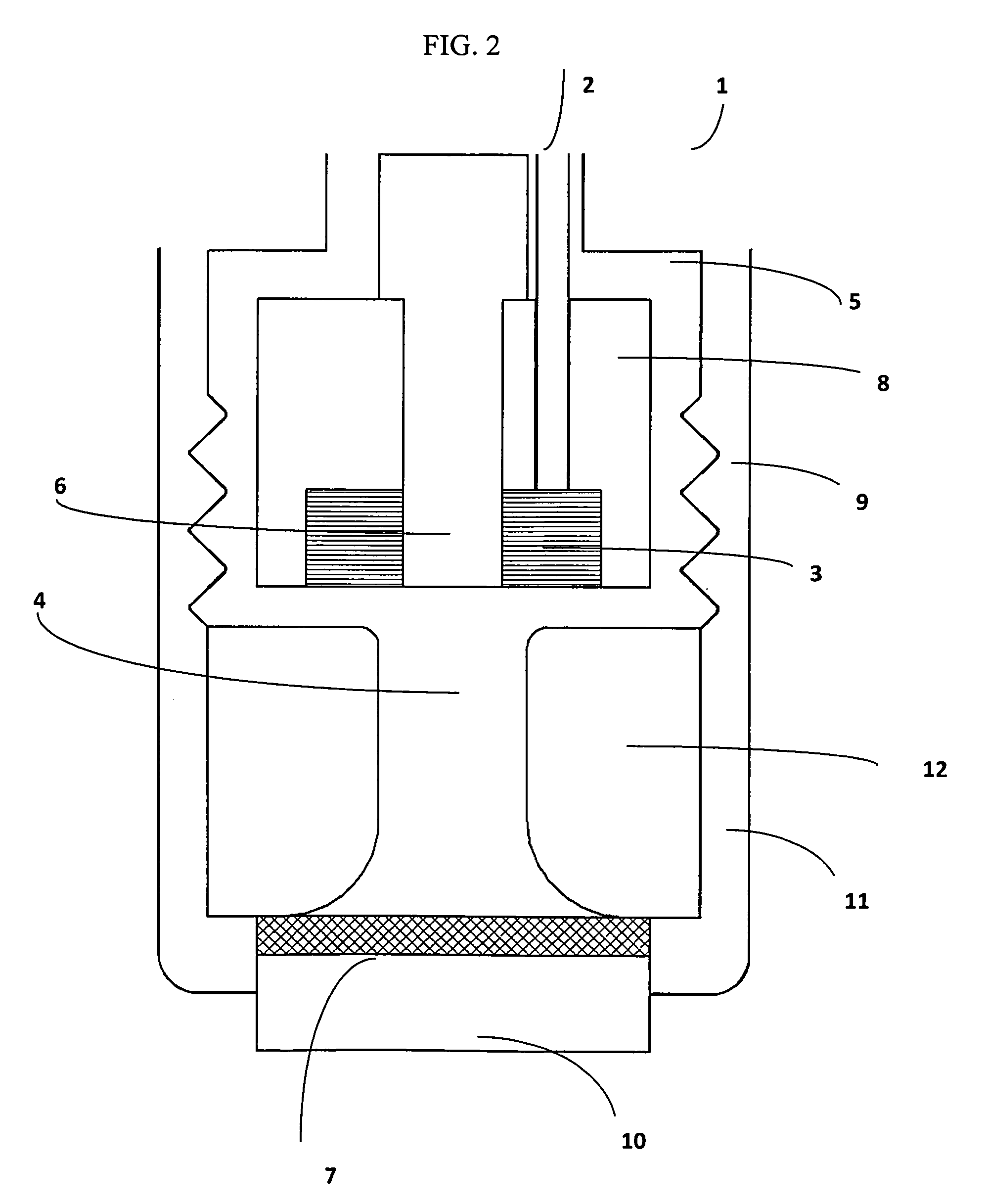
[0089]With reference to FIGS. 1 and 2, a hybrid burner 1 was constructed of stainless steel and operated in accordance with this invention. A fuel inlet path 2 was provided terminating in an orifice (0.063 inch; 1.6 mm diameter) in direct contact with one of a plurality of stainless steel reticulated screens 3 in the form of a stack of donuts. Each screen 3, obtained from McMaster-Carr, comprised wire threads of diameter 0.001 inch (0.025 mm) and a total of 500 wires per square inch (77.5 / cm2). A glow plug 6 was positioned in the donut-hole of the stacked screens. A combustion catalyst 7 was positioned downstream from the screens. The catalyst 7, a Microlith® brand ultra-short-channel-length metal mesh substrate having rhodium metal deposited thereon (Precision Combustion, Inc.), was positioned in direct contact with a heat acceptor 10 comprised of a stainless steel plate (¼ inch, 6.3 mm thickness). An outlet 11 for exiting combustion gases from the burner was provided as shown in F...


PUM

PropertyMeasurementUnit
diameteraaaaaaaaaa
lengthaaaaaaaaaa
channel lengthaaaaaaaaaa

Abstract

An apparatus and process for vaporizing and, optionally, igniting a liquid fuel, preferably, a distillate fuel. The apparatus includes the following components: a heat-conductive reticulated screen positioned within a chamber; a first inlet path into the chamber for delivering a liquid fuel onto the screen; a second inlet path into the chamber for contacting an oxidant with the screen and fuel; a means for heating the screen to a temperature sufficient to vaporize and, optionally, ignite the liquid fuel; and a recuperator in fluid communication with the chamber for transferring heat from the chamber to the second inlet path. The apparatus is suitably employed in compact and portable oxidation reactors, for example, in external combustion engines, catalytic partial oxidation reformers, and hybrid combustors operating in flame and / or catalytic modes.

Description

CROSS-REFERENCE TO RELATED APPLICATIONS[0001]This application is a 371 filing of International Patent Application PCT / US2012 / 000029, filed Jan. 18, 2012, which claims the benefit of U.S. provisional patent application Ser. No. 61 / 462,396, filed Feb. 1, 2011.GOVERNMENT RIGHTS[0002]This invention was made with support from the U.S. government under Contract No. W15P7T-08-C-K401. The U.S. government holds certain rights in this invention.FIELD OF THE INVENTION[0003]In one aspect, this invention pertains to a method and apparatus for vaporizing and, optionally, igniting a liquid fuel. In another aspect, this invention pertains to an oxidation reactor, such as a combustor or fuel reformer, incorporating as one of its components the apparatus for vaporizing and, optionally, igniting a liquid fuel.BACKGROUND OF THE INVENTION[0004]Oxidation reactors and processes can be classified into two types. One type of apparatus comprises a combustor or burner for burning a fuel with an oxidant, such ...

Claims


Application Information

Patent Timeline
Patent Type & Authority Patents(United States)
IPC IPC(8): F23D3/00F23D11/44F23L15/04F23C13/02C01B3/38F23D3/40
CPCC01B3/386F23C13/02F23D11/443F23D11/448F23L15/04F23D11/441C01B2203/0261C01B2203/1288Y02E20/34
Inventor MASTANDUNO, RICHARDSPENCE, DAVIDROYCHOUDHURY, SUBIRCROWDER, BRUCE
Owner PRECISION COMBUSTION
Why Eureka
Try Eureka