Fluid pressure control apparatus/process

a technology of fluid pressure control and control apparatus, which is applied in fluid pressure control, process and machine control, etc., can solve the problems of inability to determine the quantity of hysteresis correction adequately, and achieve the effect of reducing or eliminating the hysteresis effect, improving the accuracy of pressure control, and reducing the hysteresis effect of a hysteresis characteristi

Active Publication Date: 2012-04-03
JATCO LTD +1
View PDF12 Cites 4 Cited by
  • Summary
  • Abstract
  • Description
  • Claims
  • Application Information

AI Technical Summary

Benefits of technology

[0004]Therefore, it is an object of the present invention to provide technique, such as apparatus and / or process, for improving the accuracy in the pressure control with a correction for reducing or eliminating hysteresis effect in accordance with variation of the hysteresis quantity.

Problems solved by technology

Therefore, when the current is turned at an intermediate position before the greatest current value producing the highest output pressure, the control system of the above-mentioned document is unable to determine a hysteresis correction quantity adequately in conformity with the actual hysteresis quantity, and control the fluid pressure accurately.

Method used


Image

  • Fluid pressure control apparatus/process
  • Fluid pressure control apparatus/process
  • Fluid pressure control apparatus/process

Examples


second embodiment

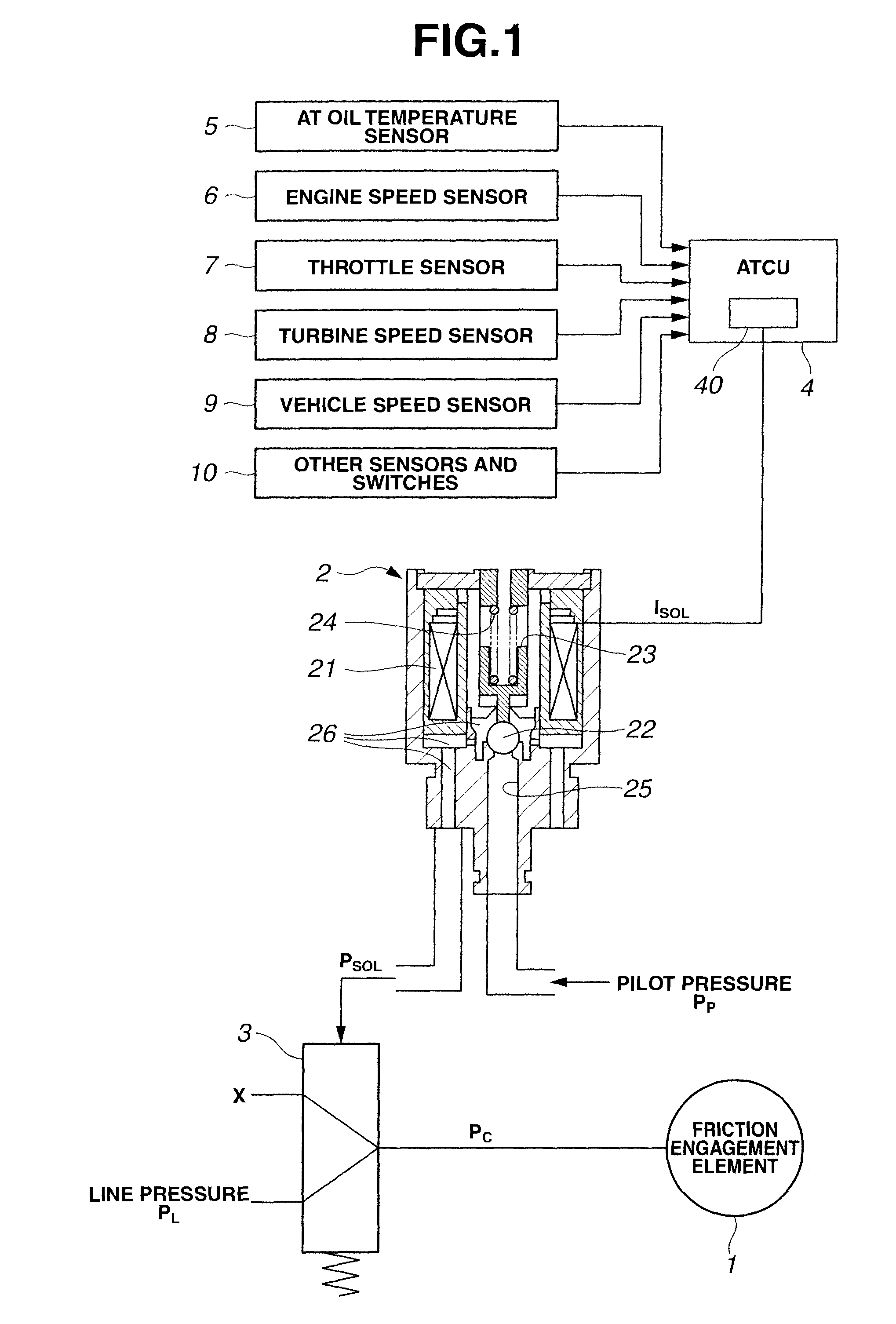
[0086]A fluid pressure control system according to a second embodiment is a control system for controlling the fluid pressure of a friction engagement element in an automatic transmission for a vehicle, and the control system of the second embodiment has the same construction as the fluid pressure control system of the first embodiment as shown in FIG. 1.

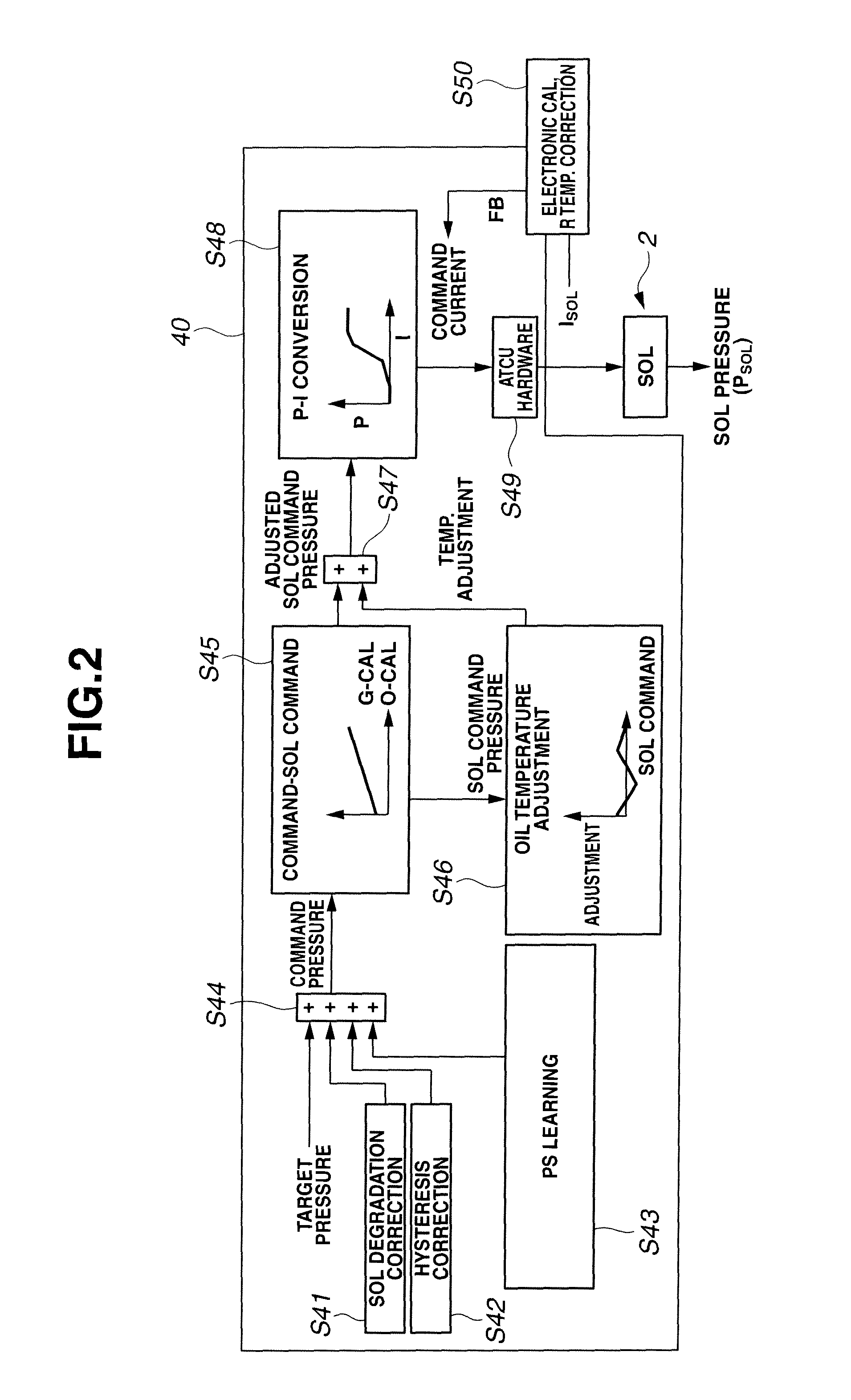
[0087]FIG. 11 is a control block diagram for illustrating the flow of the hysteresis pressure correction quantity calculating process in the clutch pressure correcting section 40 of automatic transmission control unit 4 according to the second embodiment. This hysteresis pressure correction quantity calculating process includes the following steps.

[0088]A step S500 is a differentiating step for determining a command current variation quantity of the command current as the correction input. In this example, the command current variation quantity is determined by a differentiating operation by differentiating the command current.

[0089...


PUM


Abstract

A fluid pressure control apparatus for controlling a solenoid valve to increase and decrease a fluid pressure by varying a valve opening degree includes a controller to control the fluid pressure by varying a command current for driving the solenoid valve. The controller calculates a hysteresis correction quantity to reduce a hysteresis effect of a hysteresis characteristic of the fluid pressure outputted from the solenoid valve with respect to the command current varied in an increasing direction and a decreasing direction, and varies the command current to control the fluid pressure to a target pressure in accordance with the hysteresis correction quantity. The controller calculates the hysteresis correction quantity in accordance with a turn-to-turn variation quantity determined from a current difference between a first command current value at a first changeover of a varying direction of the command current from one of the increasing and decreasing directions to the other and a second command current value at a second changeover of the varying direction of the command current before the first changeover.

Description

BACKGROUND OF THE INVENTION[0001]The present invention relates to fluid pressure control apparatus and / or process for controlling a fluid pressure with a solenoid valve.[0002]In the case of a solenoid valve for controlling a fluid pressure, the behavior of the output pressure of the solenoid valve with respect to a solenoid drive current exhibits hysteresis between the current increasing side and decreasing side. Therefore, a Japanese patent document JP2003-294126A proposes a solenoid valve control system using predetermined measurement map of actual values of the output pressure for each of current values, obtained by measurement when the current is increased until the output pressure is increased to a highest pressure value and then the current is decreased until the output pressure is decreased to a minimum setting equaling zero. This solenoid valve control system controls the solenoid drive current by using a characteristic map representing a relationship between an output press...

Claims


Application Information

Patent Timeline
Patent Type & Authority Patents(United States)
IPC IPC(8): G06F19/00F16K51/00
CPCF15B21/087F16D48/066G05D16/2093F16H61/0251F16D2500/1026F16D2500/3022F16D2500/5018F16D2500/70406F16D2500/70418F16D2500/3024F16D48/00F16D48/06F16H61/00F16H61/02F16H61/04F16H61/10
Inventor HINAMI, TAKASHIGEMORITA, YOSHIO
Owner JATCO LTD
Why Eureka
Try Eureka