Suspension arm

a suspension arm and arm technology, applied in mechanical devices, couplings, transportation and packaging, etc., can solve the problems of high rigidity of the suspension arm and low cost competitiveness of the lightweight, and achieve the effect of high rigidity

Active Publication Date: 2012-04-10
HYUNDAI MOTOR CO LTD +1
View PDF36 Cites 9 Cited by
  • Summary
  • Abstract
  • Description
  • Claims
  • Application Information

AI Technical Summary

Benefits of technology

[0012]Various aspects of the present invention are directed to provide a suspension arm with high rigidity and lightweight at a competitive price.
[0015]A burr may be formed to the metal ball housing and protrudes with a predetermined thickness in order for the reinforcement member to enhance coupling force.
[0023]At least a connection reinforcement hole may be formed along the metal connecting portion in order that the reinforcement member is inserted into the at least a connection reinforcement hole to enhance coupling force.
[0026]As described above, a suspension arm according to an exemplary embodiment of the present invention can be formed by metal material and synthetic resin material so that the suspension arm may have high rigidity and lightweight at a competitive price.

Problems solved by technology

The suspension arm requires high rigidity against vibration and lightweight so that materials for the suspension arm are changed from steel to aluminum or plastic and also the suspension arm with high rigidity and lightweight is not cost competitive.

Method used


Image

  • Suspension arm
  • Suspension arm
  • Suspension arm

Examples


Embodiment Construction

[0037]Reference will now be made in detail to various embodiments of the present invention(s), examples of which are illustrated in the accompanying drawings and described below. While the invention(s) will be described in conjunction with exemplary embodiments, it will be understood that present description is not intended to limit the invention(s) to those exemplary embodiments. On the contrary, the invention(s) is / are intended to cover not only the exemplary embodiments, but also various alternatives, modifications, equivalents and other embodiments, which may be included within the spirit and scope of the invention as defined by the appended claims.

[0038]Exemplary embodiments of the present invention will hereinafter be described in detail with reference to the accompanying drawings.

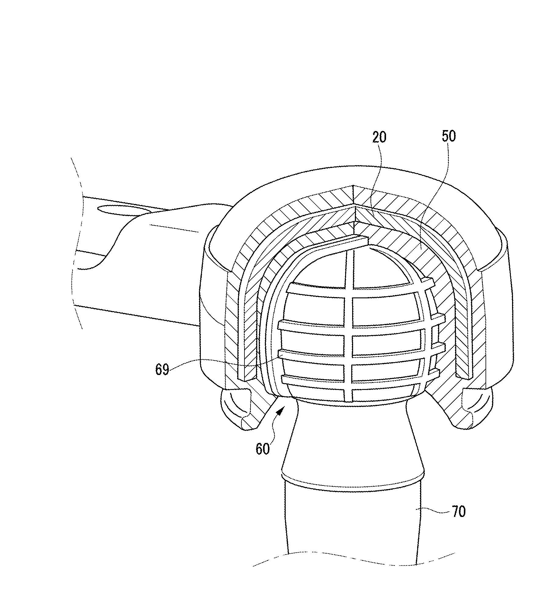
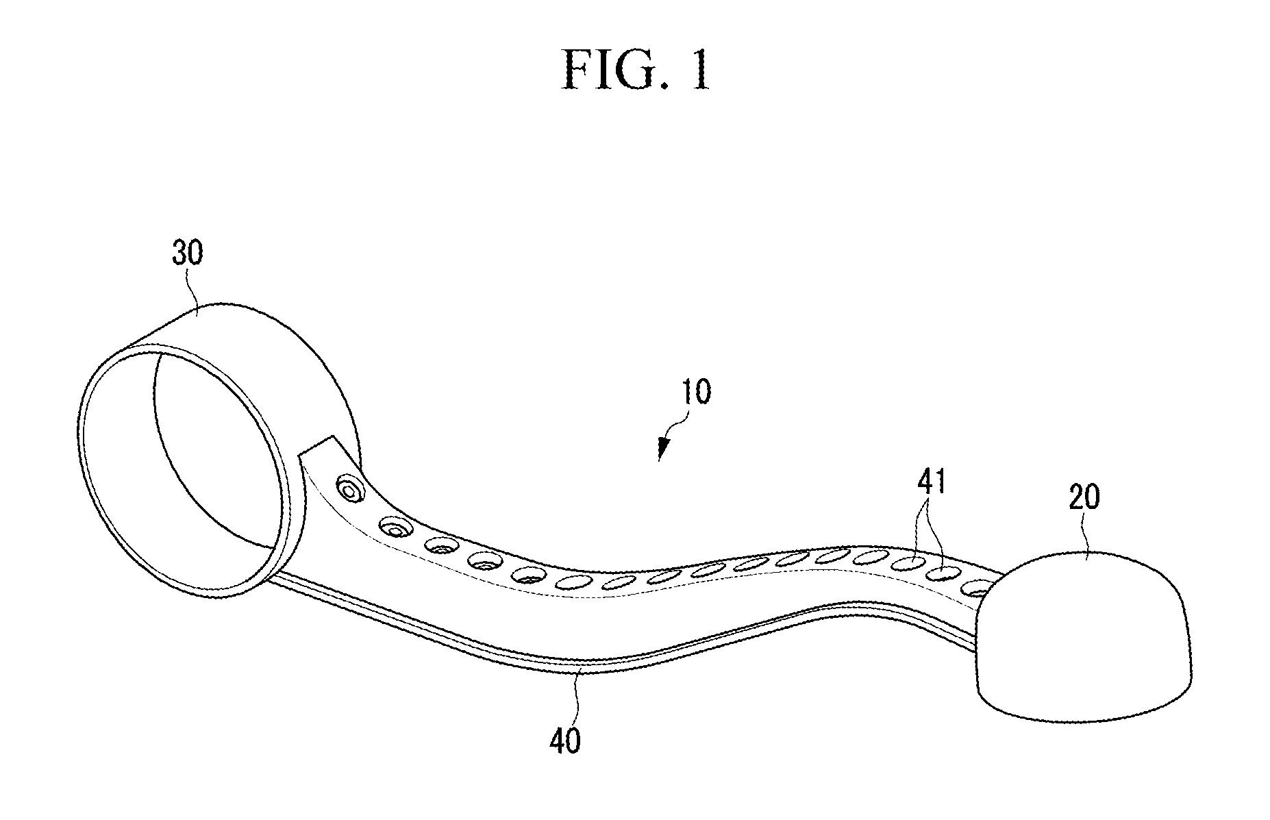
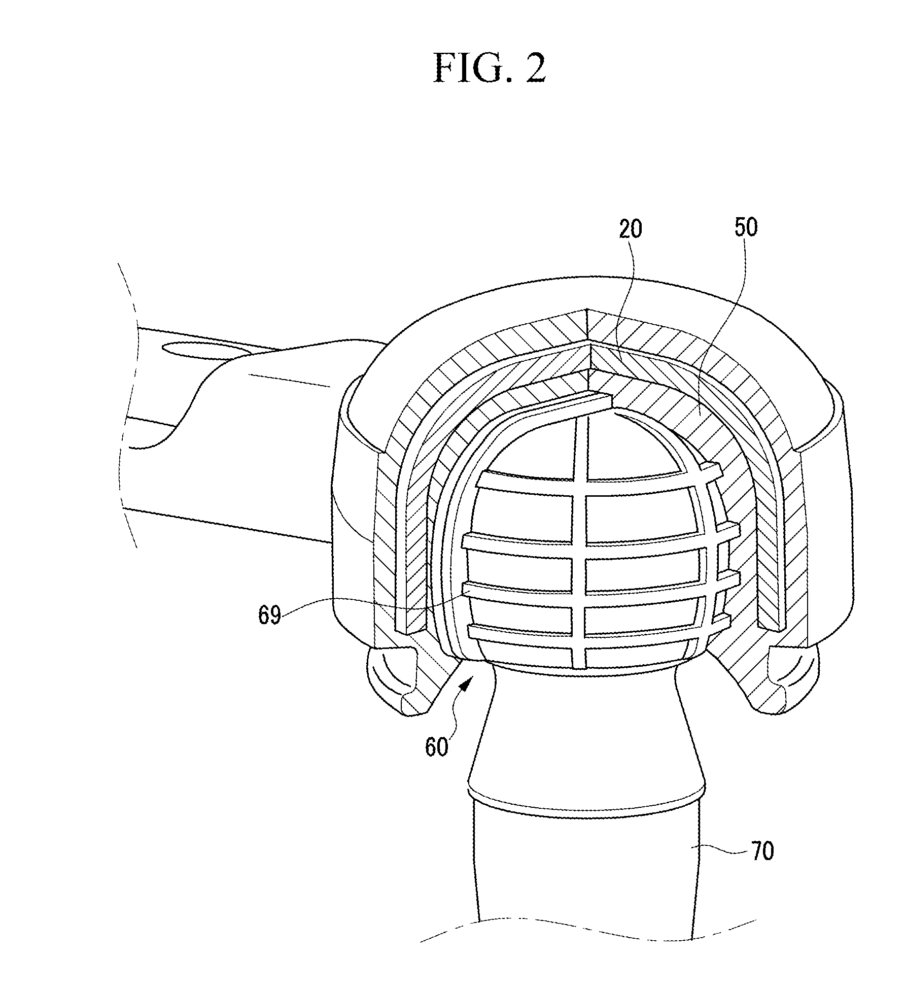
[0039]FIG. 1 is a perspective view of a metal ball housing, a metal bushing housing and a metal connecting portion of a suspension arm according to the first exemplary embodiment of the present inven...


PUM

PropertyMeasurementUnit
thicknessaaaaaaaaaa
coupling forceaaaaaaaaaa
lengthaaaaaaaaaa

Abstract

A suspension arm may include a metal portion including a hemispherical metal ball housing, a metal bushing housing, and a metal connecting portion, one end of the metal connecting portion being connected to the metal ball housing and the other end of the metal connecting portion being connected to the metal bushing housing, a bearing, made of synthetic resin material, disposed in and coupled to the metal ball housing, a ball stud, one end of which is disposed in and coupled to the bearing, and a reinforcement member, made of synthetic resin material, wrapping the metal portion and connecting the bearing to the metal ball housing.

Description

CROSS-REFERENCE TO RELATED APPLICATION[0001]The present application claims priority to Korean Patent Application No. 10-2009-0120128 filed on Dec. 4, 2009, the entire contents of which is incorporated herein for all purposes by this reference.BACKGROUND OF THE INVENTION[0002]1. Field of the Invention[0003]The present invention relates to a suspension system for a vehicle. More particularly, the present invention relates to a suspension arm made of metal and synthetic resin material.[0004]2. Description of Related Art[0005]Generally, a suspension system for a vehicle includes a chassis spring, which connects a vehicle body and an axle and relieves impacts transmitted from ground, a shock absorber, which is designed to smooth out or damp shock impulse, and dissipate kinetic energy, and a stabilizer, which relieves oscillation of a vehicle.[0006]A suspension system may be divided into a front suspension system and a rear suspension system according to mounting position, and the front s...

Claims


Application Information

Patent Timeline
Patent Type & Authority Patents(United States)
IPC IPC(8): F16C11/06F16C11/08B60G3/04
CPCB29C45/14778B60G7/001B60G7/005F16C11/0638B29C2045/14327B29K2705/00Y10T403/32786B60G2206/71B60G2206/72Y10T403/32729Y10T403/32713B60G2206/11F16C2326/05B60G3/02B60G3/00
Inventor JEONG, PIL YOUNG
Owner HYUNDAI MOTOR CO LTD
Why Eureka
Try Eureka