Vacuum platen mechanism and fluid droplet discharge device

a vacuum platen and fluid droplet technology, which is applied in the field of vacuum platen mechanism and fluid droplet discharge device, can solve the problems of large air leakage from the suction holes on both sides of the paper width, more complex vacuum control, and more complex vacuum mechanism, and achieve the effect of reducing the air leakage from the first suction hol

Active Publication Date: 2012-04-10
SEIKO EPSON CORP
View PDF20 Cites 7 Cited by
  • Summary
  • Abstract
  • Description
  • Claims
  • Application Information

AI Technical Summary

Benefits of technology

[0026]The invention renders a first suction area in which a middle strip of the platen surface is divided into a grid with the bottom of each chamber in the grid forming a rectangular first suction hole; the aperture ratio is therefore extremely high and suction in this area is strong. Moreover, by so disposing the first suction area, substantially all of the first suction holes in the first suction area are covered by the recording paper even when recording paper with a narrow paper width is conveyed, and air leakage from the first suction holes can be minimized. The vacuum pressure can therefore be prevented from particularly dropping even when recording paper with a narrow paper width is pulled to the platen.
[0027]In addition, because both edges on opposite sides of the width of wide recording paper are drawn to the platen surface in the second suction area by the vacuum pressure from the second suction holes, the right and left edges of the recording paper can be prevented from lifting up. As a result, recording paper of various paper widths can be held and conveyed flat without adjusting the vacuum pressure of the vacuum fan. The configuration and control of the vacuum mechanism can therefore be simplified and a low device cost can be achieved.

Problems solved by technology

As a result, air leakage from the suction holes on both sides of the paper width is great even after the leading end of the recording paper reaches a position near the downstream end (front end) of the vacuum platen in the transportation direction, and, as a result, the vacuum pressure may be outside the suitable pressure range Pa.
However, applying such adjustment control and providing such an adjustment mechanism makes vacuum control more complex, or results in a more complex vacuum mechanism and increased parts cost.

Method used


Image

  • Vacuum platen mechanism and fluid droplet discharge device
  • Vacuum platen mechanism and fluid droplet discharge device
  • Vacuum platen mechanism and fluid droplet discharge device

Examples


Embodiment Construction

[0036]A roll paper printer (fluid droplet discharge device) having a vacuum platen mechanism according to a preferred embodiment of the invention is described below with reference to the accompanying figures.

[0037]General Configuration

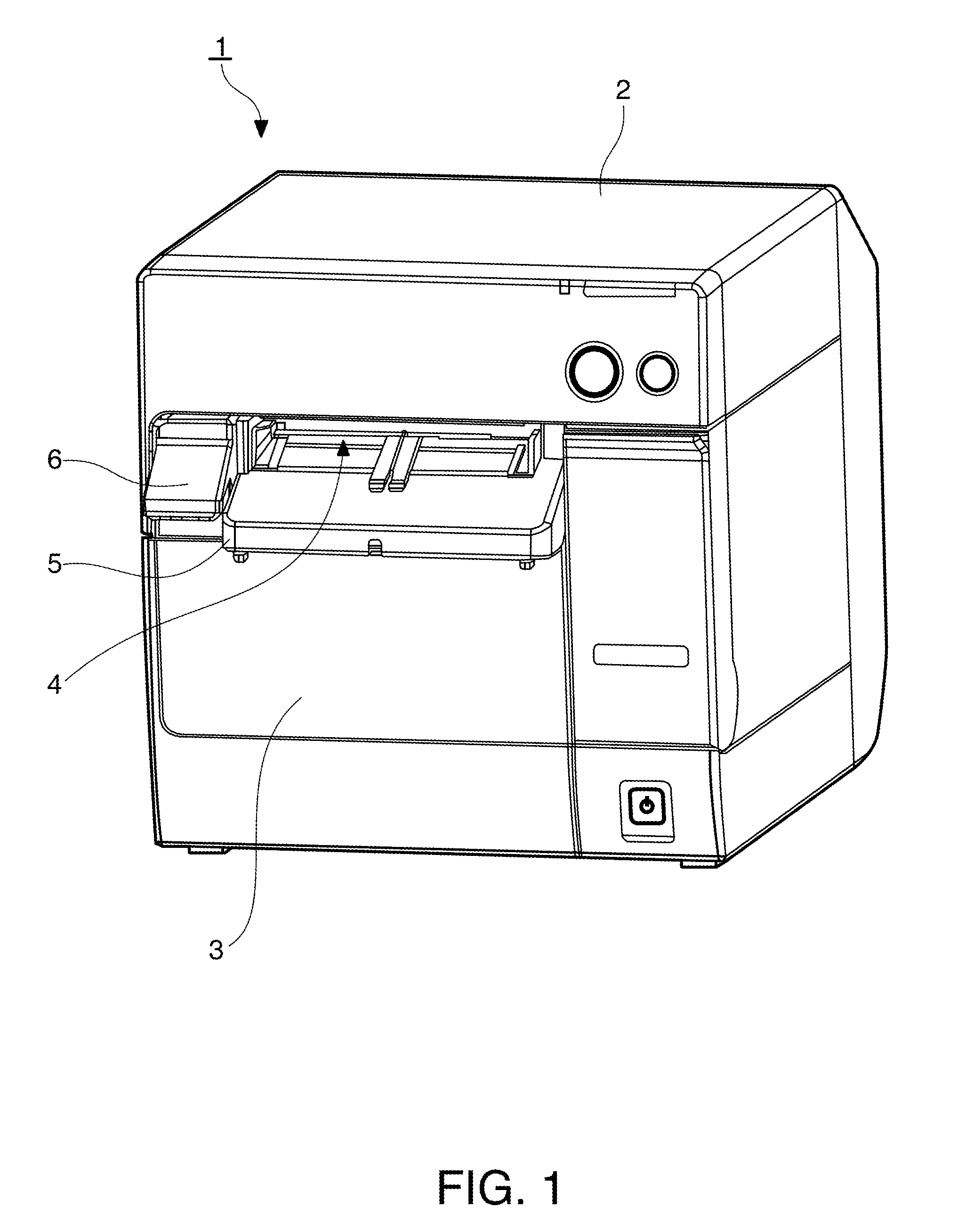
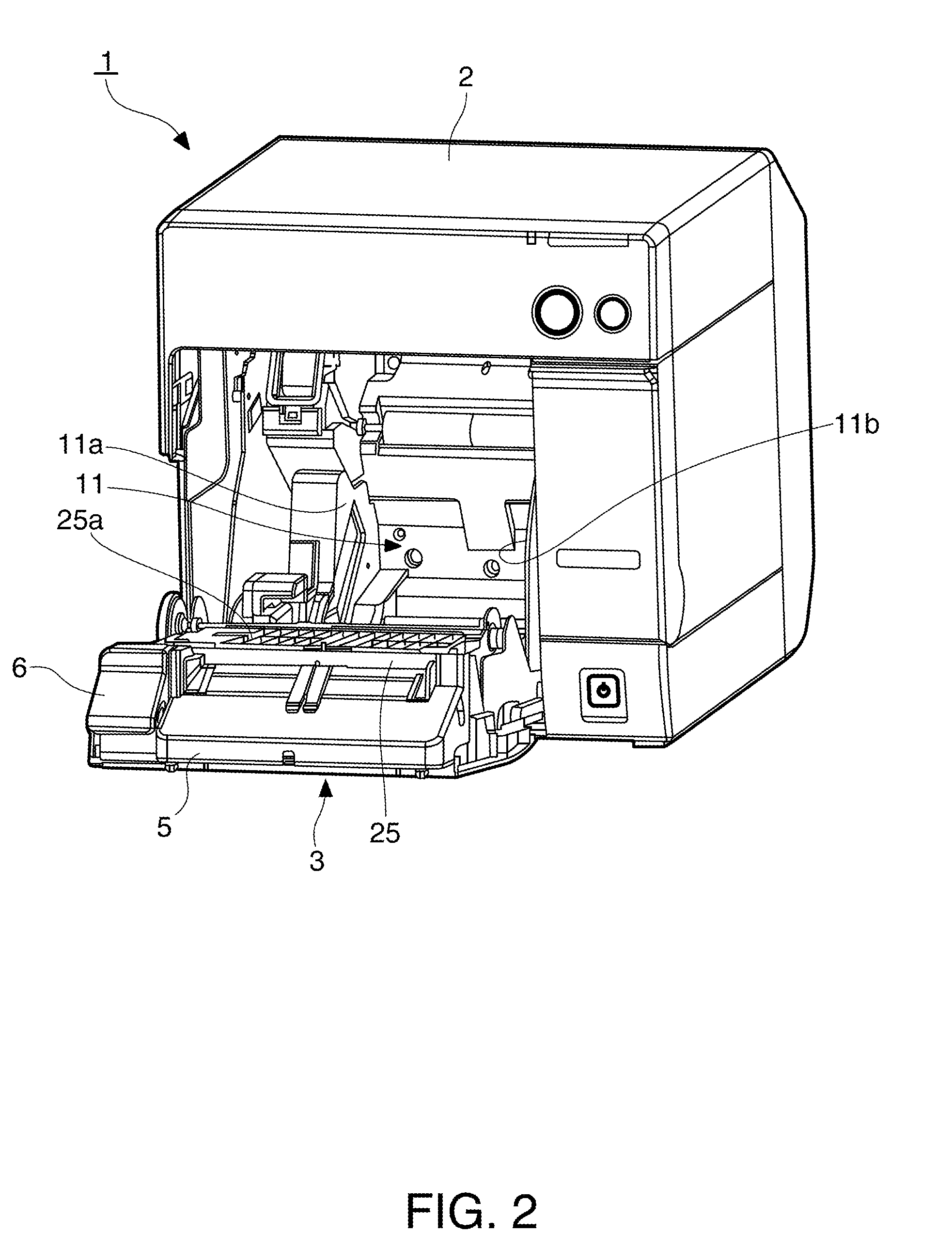
[0038]FIG. 1 is an oblique view showing an inkjet roll paper printer according to a preferred embodiment of the invention. FIG. 2 is an oblique view of the printer with the cover completely open.

[0039]The roll paper printer 1 has a rectangular box-like body 2 and an access cover 3 that opens and closes and is disposed to the front of the body 2. A recording paper exit 4 of a specific width is formed at the front of the outside case of the printer body 2. An exit guide 5 projects to the front from the bottom of the paper exit 4, and a cover opening lever 6 is disposed beside the exit guide 5. A rectangular opening for loading and removing roll paper is formed below the exit guide 5 and cover opening lever 6, and this opening is closed by the cover 3.

[00...


PUM


Abstract

Mechanism for producing vacuum pressure and air flow for drawing recording paper of various widths to the platen surface of a printer enables such pressure and air flow to be held in a suitable range without adjusting the suction. A first suction area with the same width as the minimum width of the recording paper is disposed width-wise in the middle of the platen surface that opposes the inkjet head of the printer, and second suction areas are disposed on the left and right sides of the first suction area. The first suction area is divided into a grid by intersecting ribs to form first chambers, each having a first suction hole formed in a bottom thereof that communicates with a vacuum channel. The second suction areas are also segmented to form second chambers. Second suction holes are selectively formed in some, but not all, of the second chambers and are appropriately spaced from the first suction holes. The front edge of the first suction area is offset slightly from the front edge of the second suction areas.

Description

CROSS-REFERENCE TO RELATED APPLICATION(S)[0001]Japanese Patent application No. 2009-047673 is hereby incorporated by reference in its entirety.BACKGROUND[0002]1. Field of Invention[0003]The present invention relates to a fluid droplet discharge device such as a printer that has a vacuum platen that pulls recording paper to a platen surface that determines the printing position, and relates more particularly to an improved suction hole and the surface configuration of the vacuum platen.[0004]2. Description of Related Art[0005]Holding the recording paper tight to the platen surface that defines the printing position and maintaining a precise platen gap is important in order to ensure print quality in an inkjet printer, which discharges ink droplets to print on the recording paper. Therefore, in order to so hold the recording paper while it is conveyed, a vacuum platen is used to pull the recording paper to the platen surface by means of air suction while the recording paper is conveye...

Claims


Application Information

Patent Timeline
Patent Type & Authority Patents(United States)
IPC IPC(8): B41J2/01
CPCB41J11/0025B41J11/0085B41J11/02B41J11/06
Inventor MAEKAWA, HIRONORIOYA, SHUN
Owner SEIKO EPSON CORP
Why Eureka
Try Eureka