Method of operation of a spherical positive displacement rotary machine and devices for carrying out said method

a positive displacement, rotary machine technology, applied in the direction of rotary or oscillating piston engines, rotary piston engines, engine lubrication, etc., can solve problems such as possible jamming, weakening of shafts, and non-uniform flow ra

Inactive Publication Date: 2012-04-10
DIDIN ALEXANDR VLADIMIROVICH +1
View PDF20 Cites 11 Cited by
  • Summary
  • Abstract
  • Description
  • Claims
  • Application Information

AI Technical Summary

Problems solved by technology

Disadvantage of such machines is a complicated configuration of the separator and the piston through-cutout that does not allow contact between them over a large area in order to reduce wear of the friction pair (to reduce an ideal load on the friction pair and extend its service life).
PDRM also has disadvantages: the difficulty of combining such a machine into a multistage machine, associated with the fact that the inlet and outlet openings are located on the same side of the piston, and in order to get from one stage to another, a channel is required bypassing the spherical cavity of the body along the rotor axis.
Also considered as disadvantages are: non-uniform flow rate, weak mounting of the piston (which is only partially located inside the groove on the sphere), which also weakens the shaft due to the circular groove, unreliable mounting of the sealing synchronizing element in the through-cutout of the piston (jamming is possible under increased loads).
Unreliable synchronizing mechanism, especially in case if the gear shaft is required to pass through several stages, is referred to as disadvantage.
Besides, the piston is not desirable to be made too thick.
Moreover, angular dimension of the passes along the movement of the piston is limited (otherwise, the separator does not close off the piston through-cutout) resulting in working medium flow resistance increase.
This results in increase of the working medium pass size, reducing the machine hydraulic resistance.
And in many cases, this produces wear margin for the through-cutout and the separator, excluding the occurrence of the gap leakage.
2) The shutter lug moves all the time inside a guide groove, made on the body spherical surface, and entirely regulates the shutter position. The disadvantage is that the groove presence results in increase of the machine diameter (it is important for submersible embodiments) and leads to abrasive accumulation in it and rubbing of the lug. The lug rubbing results in seal deterioration.
3) The position of the shutter is controlled by a guide, situated along the body at the propulsion area. The disadvantage is that the piston through-cutout shall also pass this guide through; therefore, it is bigger in size which results in increase of the shutter size and its load. A wear of the shutter cutout and the guide results in the seal deterioration.
4) The shutter is controlled by the angle of the separator, located from the opposite side of the piston. For example, when the SSE, the axis of which goes through the piston center at right angle to the piston axis, acts as the shutter. The disadvantage is that along a sufficiently large transition area the angle of the separator is changed slowly delaying the closing off process.
5) The shutter is controlled by the thickness of the separator, located from the opposite side of the piston. The disadvantage is that it results in an increase of the separator thickness, the piston through-cutout height and the shutter dimensions.
6) The most interesting case is, when the shutter is controlled by the piston position relative to the rotor. The shutter is required to be brought into open position just at one point—at the place of the maximum deviation of the piston through-cutout, for example, downwards (if the shutter is located higher than the through-cutout is). In all the other positions, it is closed provided that it is not positioned at the separator. The advantage is that the piston speed relative to the rotor is not high (it is equal to zero at the center) and this place is protected against abrasive to a greater extent (by means of centrifugal forces, seals). The simplest way of controlling is to make a groove in the form of an arc near the axis of the shutter and to mount a pin (stop) in the rotor. When the shutter, together with the piston, comes to the position of the separator entry, the pin reaches the end of the groove and the shutter stops, but the piston can turn further.

Method used


Image

  • Method of operation of a spherical positive displacement rotary machine and devices for carrying out said method
  • Method of operation of a spherical positive displacement rotary machine and devices for carrying out said method
  • Method of operation of a spherical positive displacement rotary machine and devices for carrying out said method

Examples


Embodiment Construction

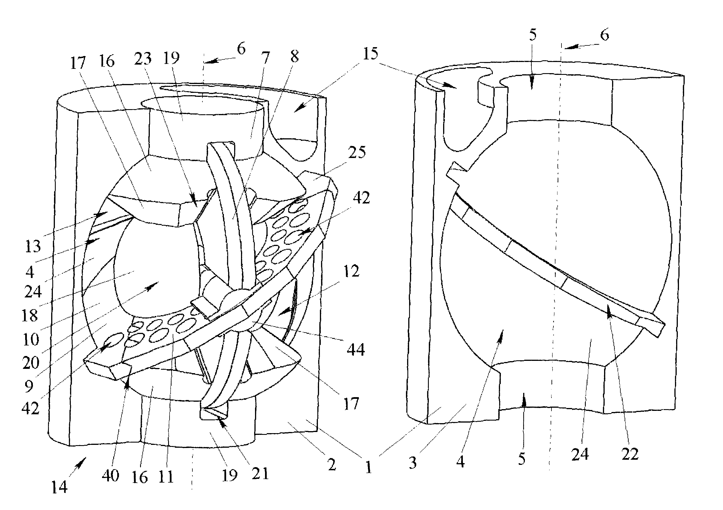
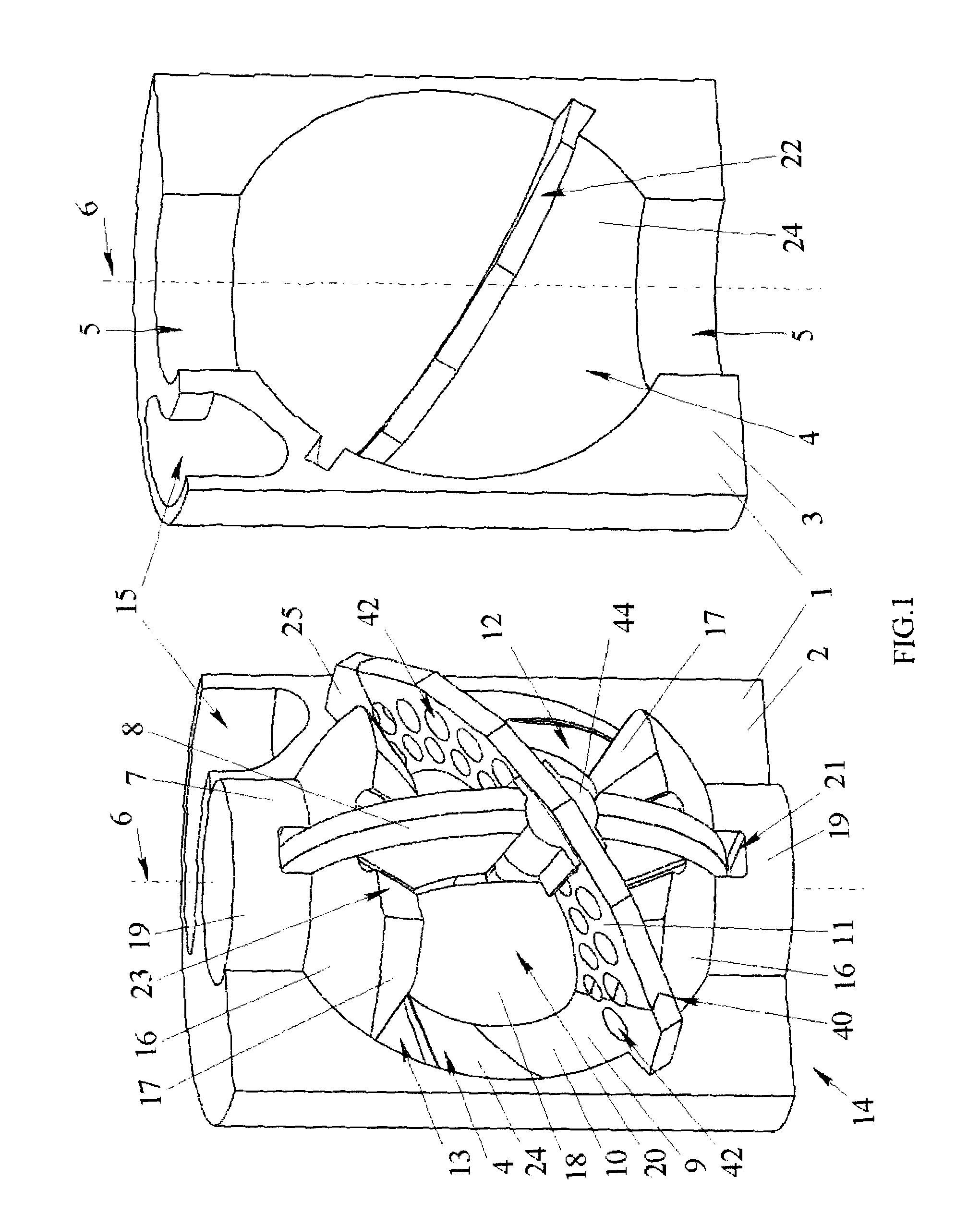
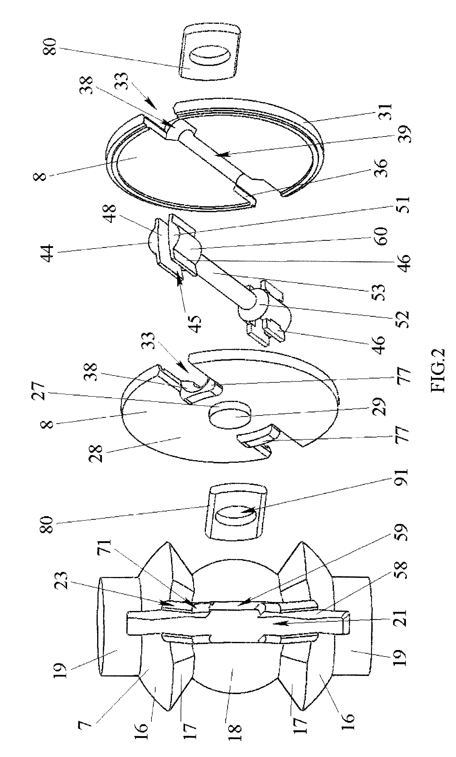
[0155]A stage (which can be used separately as well) of the positive displacement rotary machine (FIG. 1) is structured as follows. A body 1 (FIG. 1, 13), made of two parts, conventionally called the ascending (bypass) half 2 and the descending (propulsion) half 3, contains a cavity 4 in the form of a segment of a sphere (rather a segment of a torus, which is formed instead of the sphere resulting from tolerances for the rotor axial clearance) with two holes 5, concentric with it. A separator 9 (FIG. 1, 3), made in the form of a washer with the inner spherical hole 41, is mounted in the spherical cavity 4 at an angle to the hole 5 geometrical axis which is the machine geometrical axis 6. By functions, the separator 9 can be conventionally divided into two areas: the ascending (bypass) 10 running upwards at the bypassing of the rotor from right to left, and the descending (propulsion) 11 running downwards at the bypassing of the rotor from right to left. Although for strength, it is ...


PUM


Abstract

A positive displacement rotary machine with a body having an internal spherical working surface divided into bypass and propulsion areas, a rotor with a working rotational surface, a ring working cavity formed by the working surfaces of the body and rotor, and a C-shaped separator mounted in part of the cavity at an angle to a plane of the rotor rotation. The cavity is partitioned by the separator at the bypass area, and the working medium openings are located from opposite sides of the separator. The working surface of the rotor has at least one slot. In each slot is mounted a piston capable of sealing the working cavity, and performing rotational oscillations in a slot plane. The piston is at least in the form of a part of a disk and has at least one through-cutout for the separator passage, and can seal the through-cutout at the propulsion area.

Description

CROSS-REFERENCE TO RELATED APPLICATION[0001]This application is a continuation of and claims priority from International Application PCT / RU2007 / 000370 filed Jul. 9, 2007, which claims the benefit of Russian Patent application No. RU 2006124511 filed Jul. 10, 2006, the entire disclosure of each of which is incorporated herein by reference.FIELD OF THE INVENTION[0002]The invention relates to mechanical engineering that is to positive displacement rotary machines which can be used as pumps, compressors, hydraulic drives and others, particularly in multistage submersible units.BACKGROUND OF THE INVENTION[0003]A positive displacement rotary machine (PDRM) (RU 2004133654) having a body with an internal ring cavity is known. A spiral separator with a rotor inside is installed in this cavity. The rotor working surface is a surface of rotation, where there is at least one slot along the rotation axis of the rotor, in each of which a piston partly extending (projecting) from one side of the r...

Claims


Application Information

Patent Timeline
Patent Type & Authority Patents(United States)
IPC IPC(8): F01C3/00F03C2/00F03C4/00F04C18/00
CPCF01C9/005F04C11/001F04C13/008F04C19/001F04C15/0049
Inventor DIDIN, ALEXANDR VLADIMIROVICHYANOVSKY, ILYA YAKOVLEVICH
Owner DIDIN ALEXANDR VLADIMIROVICH
Why Eureka
Try Eureka