
Chain for a chain transmission

a technology of chain transmission and chain, which is applied in the direction of belt/chain/gearing, chain elements, belts, etc., can solve the problems of too high stress level in materials and wear on the corners of cam surfaces

Inactive Publication Date: 2012-04-17
KORSE THEODORUS HENRICUS JOHANNES CAROLINA
View PDF27 Cites 15 Cited by
  • Summary
  • Abstract
  • Description
  • Claims
  • Application Information

AI Technical Summary

Benefits of technology

"The patent describes a chain system used in stamping tools. The chain system has a curved surface with a specific radius of curvature that reduces contact stress and impact. The chain system also has a cam surface that supports the link plates without colliding with its corner on the cylindrical support surface. The chain system also includes link plates that are asymmetrical and have different lengths near the pivot axes to improve support in the area where the chain links move towards a sprocket wheel. Additionally, the chain system includes a cam surface that is parallel to the chain link axis for a part of its length to ensure a straight path for the pin axes. The chain system also includes each chain link that has at least two link plates separated by a chain bush near each pivot axis for more stable support."

Problems solved by technology

The disadvantage of the known transmission is that leaving out the straight guide that supports the cam surfaces of the chain links before being supported by the cylindrical support surface, for instance in order to save costs, can cause wear on the corners of the cam surfaces.
This wear is caused by the impact of the edge of the cam surface at the end of the chain link on the cylindrical support where the impact can create a too high stress level in the material.

Method used


Image

  • Chain for a chain transmission
  • Chain for a chain transmission
  • Chain for a chain transmission

Examples


Embodiment Construction

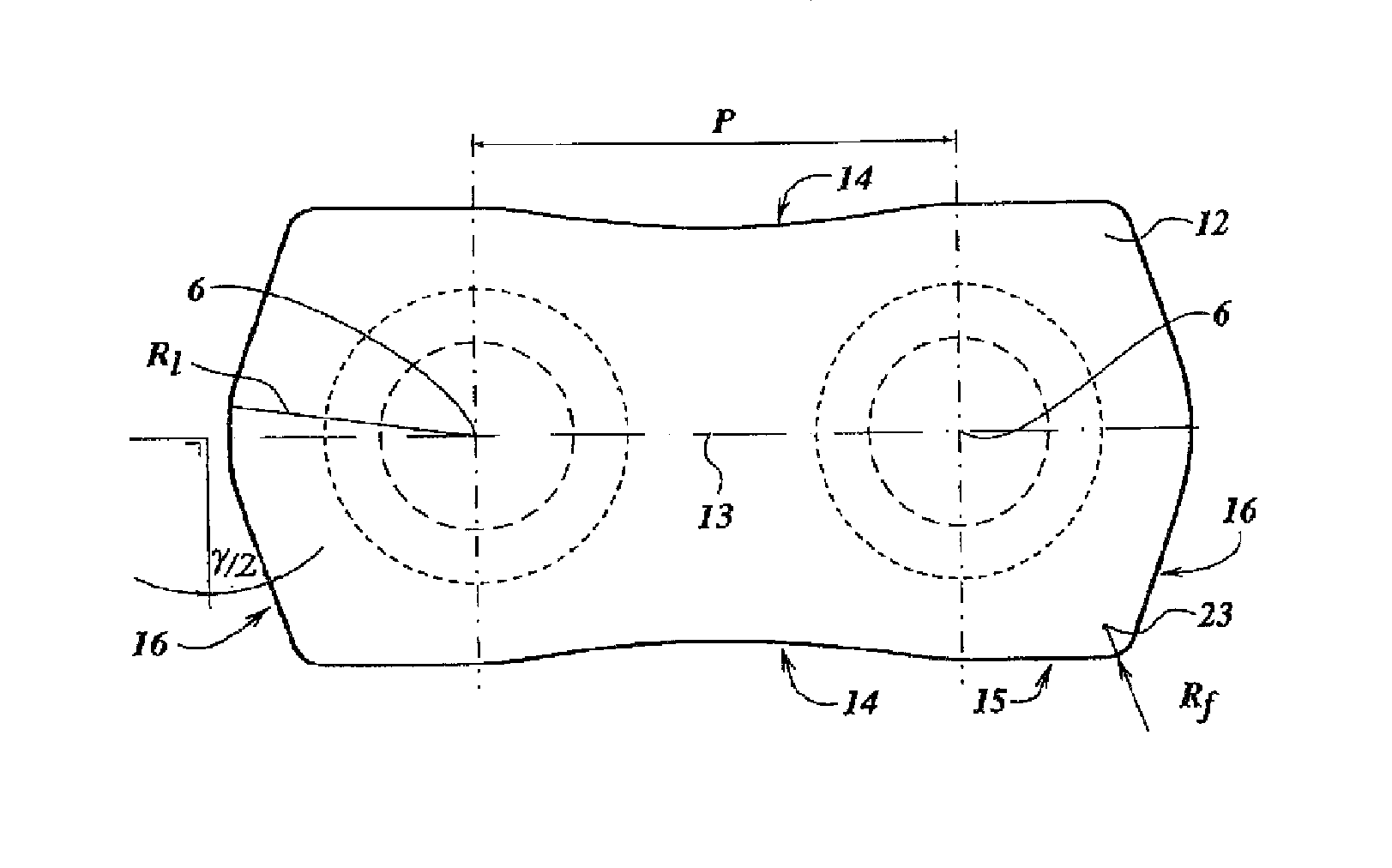
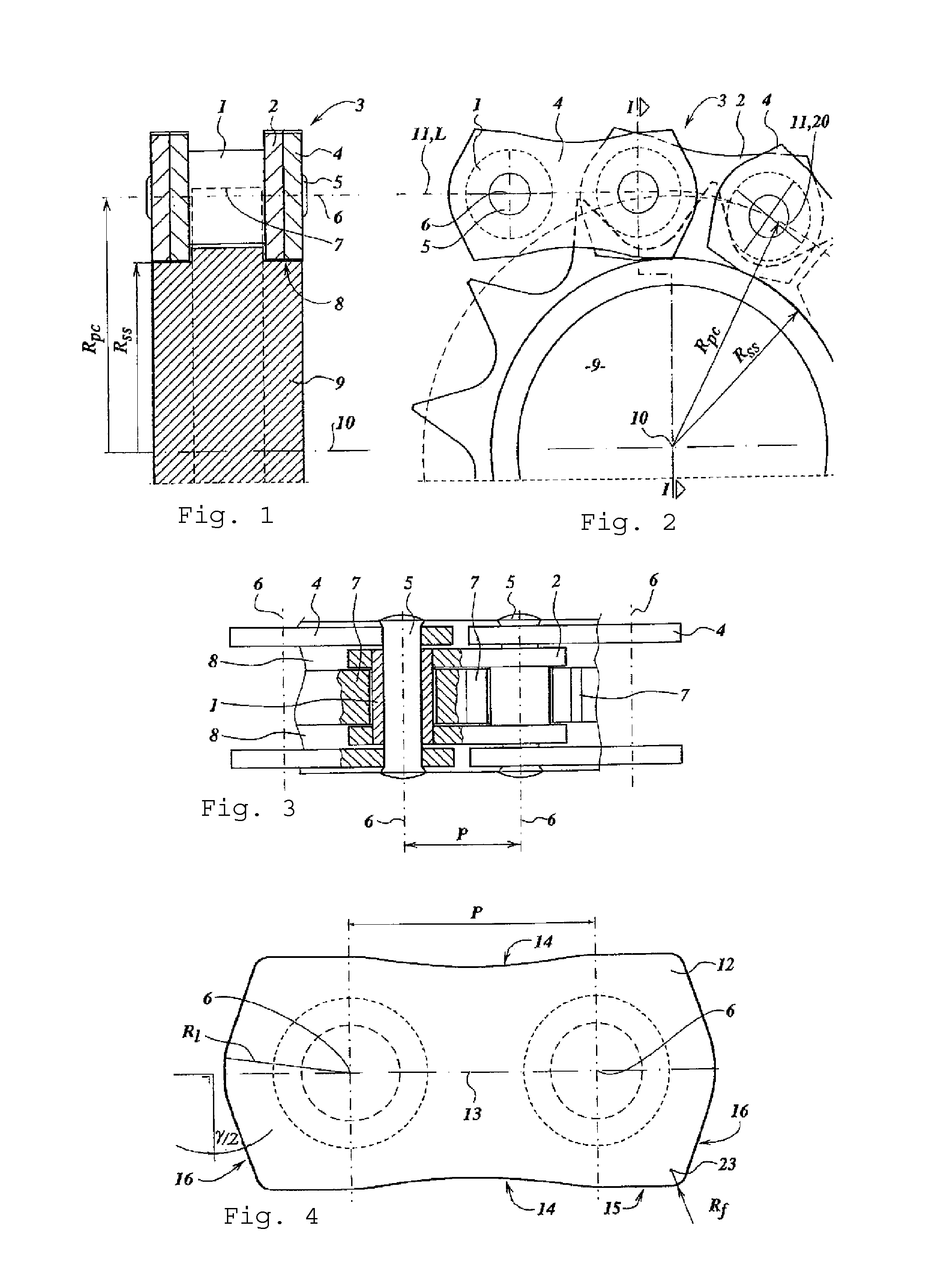
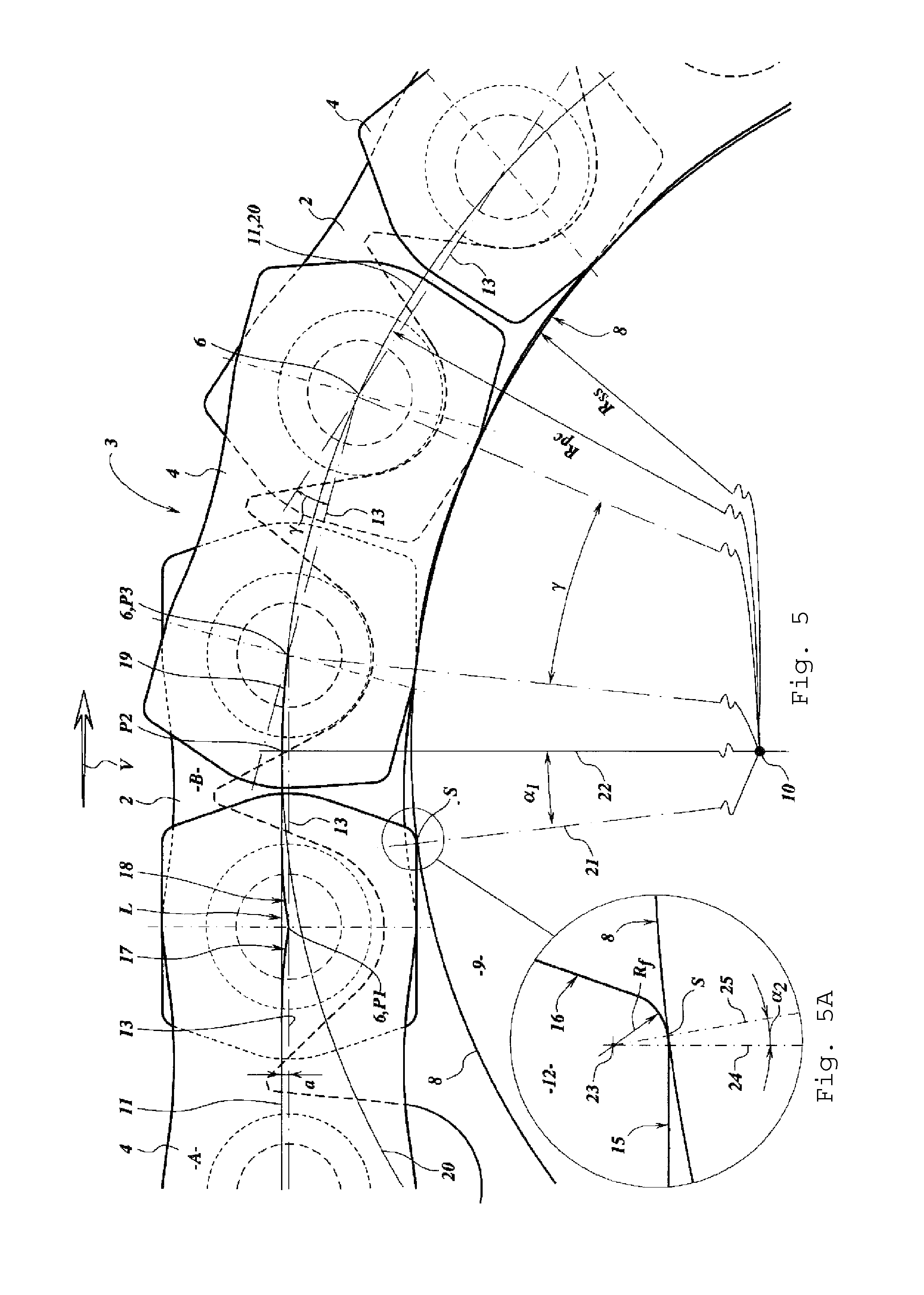
[0034]FIGS. 1, 2 and 3 show a chain 3 engaged with a sprocket wheel 9. The sprocket wheel 9 can rotate around a sprocket wheel axis 10 and is provided with sprocket teeth 7. The sprocket wheel 9 has at both sides of the sprocket teeth 7 a support surface 8 which supports the chain 3. The chain 3 is provided with inner link plates 2. Between two inner link plates 2 there are two chain bushes 1 and together the inner link plates 2 and the chain bushes 1 form an inner link. This type of chain is called a bush chain. Two inner links are connected by two outer link plates 4 using chain pins 5 whereby the inner link and the outer link plates 4 can pivot around a pin axis 6. The distance between two pin axes 6 is a pitch p. The sprocket wheel 9 has a number of sprocket teeth 7 which engage with the chain bushes 1 so that the pin axes 6 when positioned around the sprocket wheel 9 are on a pitch circle 20 with a pitch circle radius Rpc. The inner link plates 2 and the outer link plates 4 are...


PUM


Abstract

The invention concerns a chain for a chain transmission with chain links coupled by a parallel chain pins, each chain link having at least one link plate, the chain pins forming pivot axes for the link plates at a pitch distance whereby a chain link axis perpendicularly intersects the two pivot axes, said link plates having towards at least one end side of the link plate a cam surface for supporting the link plate on a cylindrical support surfaces of a sprocket wheel with a pitch angle. In accordance with the invention the cam surface ends in a convex curved plane with near the end side an increasing slope angle with the link axis whereby the slope angle increases to at least half of the pitch angle or to at least seven degrees.

Description

CROSS-REFERENCE TO RELATED APPLICATIONS[0001]The present application is a continuation of pending International patent application PCT / EP2006 / 070159, filed Dec. 22, 2006, which designates the United States and claims priority from European patent application no. 05112684.5, filed Dec. 22, 2005, the content of which is incorporated herein by reference.FIELD OF THE INVENTION[0002]The invention concerns a chain for a chain transmission with chain links coupled by parallel chain pins, each chain link having at least one link plate, the chain pins forming pivot axes for the link plates at a pitch distance whereby a chain link axis perpendicularly intersects the two pivot axes, the link plates having a cam surface for supporting the link plate on a cylindrical support surfaces of a sprocket wheel with a pitch angle.BACKGROUND OF THE INVENTION[0003]Such a chain for a chain transmission is known from WO03093700. The disadvantage of the known transmission is that leaving out the straight gui...

Claims


Application Information

Patent Timeline
Patent Type & Authority Patents(United States)
IPC IPC(8): F16G13/02F16H7/06
CPCF16G13/06F16H7/06F16G13/02
Inventor KORSE, THEODORUS HENRICUS JOHANNES CAROLINA
Owner KORSE THEODORUS HENRICUS JOHANNES CAROLINA
Learn More