Orthosis

a technology of orthosis and spondylosis, which is applied in the field of orthosis, can solve the problems of general swelling, unusability, and inability to adapt quickly and simply, and achieve the effects of saving time both for patients and patients

Inactive Publication Date: 2012-04-17
WAGNER HELMUT
View PDF12 Cites 9 Cited by
  • Summary
  • Abstract
  • Description
  • Claims
  • Application Information

AI Technical Summary

Benefits of technology

[0012]An advantage of the invention lies in the fact that the distance between the load-bearing joints can be adapted to the width of the knee in a stepless manner. For example, if the swelling of the knee fluctuates during the course of the day, the orthosis can be easily readjusted.
[0013]Another advantage is that an orthosis according to the invention can be adapted quickly and simply, which saves time both for the patient and also for medical personnel involved in fitting the orthosis.
[0014]An orthosis according to the invention also permits great variation in the distance between the load-bearing joints, such that a smaller number of types is sufficient to cover all existing knee widths. Fewer variants of the orthosis according to the invention therefore have to be kept in stock, which results in savings in terms of storage capacity.
[001

Problems solved by technology

After knee operations, the tissue in the area of the knee is generally swollen, and the swelling subsides during the healing process.
A disadvantage lies in the complicated structure of the bracing device which, in addition, is not particularl

Method used


Image

  • Orthosis
  • Orthosis
  • Orthosis

Examples


Embodiment Construction

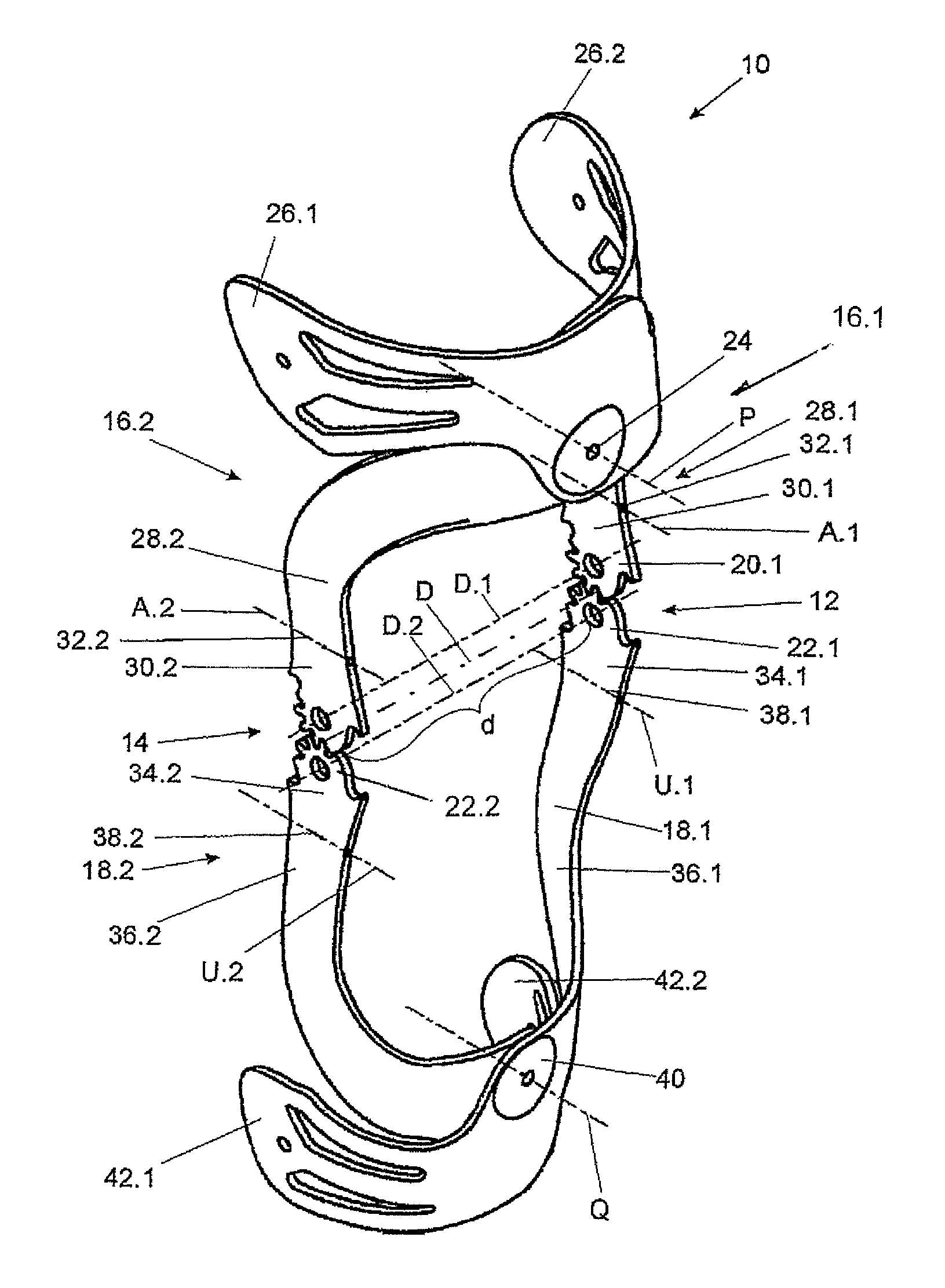
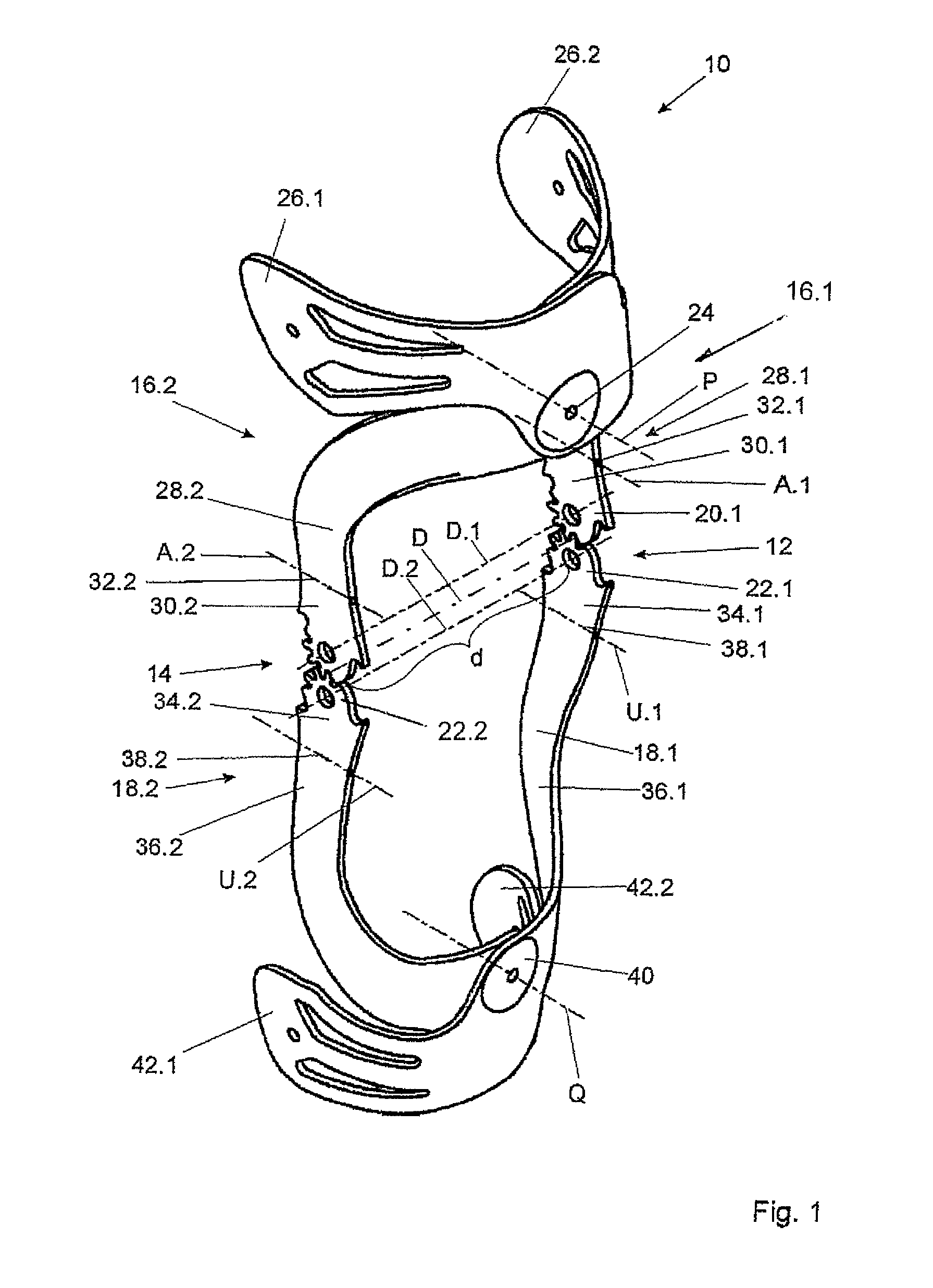
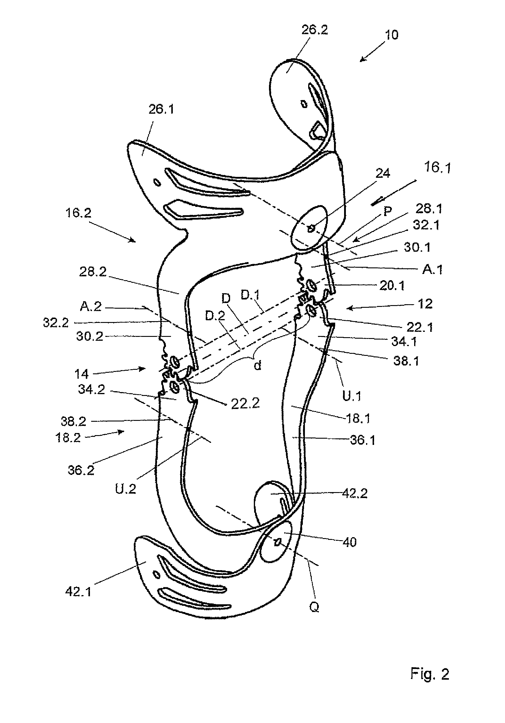
[0035]In FIG. 1, a knee orthosis 10 is shown with a left-hand load-bearing joint 12 and a right-hand load-bearing joint 14. The left-hand load-bearing joint 12 connects a left-hand proximal panel 16.1 to a left-hand distal panel 18.1 and is designed as a polycentric rotary joint. The left-hand load-bearing joint 12 comprises a proximal joint head 20.1 and a distal joint head 22.1, which each have teeth. The teeth mesh with one another when the proximal panel 16.1 pivots relative to the distal panel 18.1. The proximal and distal panels 16.1, 18.1 pivot relative to each other on a time-variable load-bearing joint pivot axis D, which always extends parallel to connecting axes D1 and D2 that connect the midpoints of the two proximal joints heads 20.1, 20.2 of the two distal joint heads 22.1, 22.2. to each other.

[0036]The proximal panel 16.1 and the distal panel 18.1 have a flat, strap-like configuration and are produced by injection molding. The knee orthosis 10 additionally comprises a...


PUM


Abstract

A knee orthodic is provided with two load-bearing joints (12, 14), each joint having a proximal leg (16.1, 16.2) and a distal leg (18.1, 18.2). The knee orthodic, may be adapted more easily to a changing knee width. This is achieved in that the proximal legs (16.1, 16.2) are connected by a proximal joint (24) and the distal joints (18.1, 18.2) are connected by a distal joint, said proximal legs (16.1, 16.2) being connected pivotally and fixably relative to one another in the proximal joint (24) in the form of a rotary joint about a proximal joint pivot axis (P).

Description

BACKGROUND OF THE INVENTION[0001]1. Field of the Invention[0002]The invention relates to an orthosis, in particular a knee orthosis, with two load-bearing joints that each have a proximal panel and a distal panel. In other words, the invention relates to an orthosis principle for different parts of the body.[0003]2. Background Description[0004]Orthoses of this kind are used to protect corresponding ligaments from overload under the effects of internal or external forces in such a way that limited and / or unlimited movements of parts of the body are possible. Knee orthoses are used to protect a knee joint from dorsoventral buckling movements. For this purpose, the knee orthosis is secured to a thigh and lower leg in such a way that the two load-bearing joints are arranged laterally of the knee joint that is to be protected. Buckling loads that occur are taken up by the knee orthosis and led past the knee into the thigh and lower leg. To ensure that buckling forces are reliably led awa...

Claims


Application Information

Patent Timeline
IPC IPC(8): A61F5/00E05D7/00E05D7/08
CPCA61F5/0123Y10T16/52A61F2005/0139
Inventor SCHIMEK, NORBERTWAGNER, HELMUT
Owner WAGNER HELMUT
Why Eureka
Try Eureka