
Image processor and image processing method processing an image that includes a semi-transparent object or an image with periodically varying density

a technology of image processing and semi-transparent objects, applied in the field of image processing methods, can solve the problems of degrading the stability of the screen, affecting the display quality, and not supporting the transparency specification command, so as to achieve the effect of reducing the variation of color tone or density

Inactive Publication Date: 2012-04-17
CANON KK
View PDF9 Cites 6 Cited by
  • Summary
  • Abstract
  • Description
  • Claims
  • Application Information

AI Technical Summary

Benefits of technology

The present invention provides an image processor and method that can minimize color tone or density variations in images after screen processing, even if semi-transparent objects are included. This is achieved by modifying the halftone value of the semi-transparent object based on the determination of whether or not it is included in the image. The processor can display the result of dither processing on the image if a semi-transparent object is included, or not. The invention also provides a computer program and storage medium for this purpose. The technical effect of the invention is to enhance reproducibility of semi-transparent objects without defying the intention of the designer and user, while also minimizing processing time and hardware requirements.

Problems solved by technology

However, there may be a situation that, depending on the type of PDL, transparency specification commands are not supported, although the application or the OS has specified transparency in response to the user's request.
This is because interference occurred between the dither processing in the intermediate process of the printer and the drawing pattern specified to be semi-transparent, whereby a part which was originally supposed to be filled is not filled.
In addition, since intermediate processes in a printer may differ according to the type of printer, interference or moire may vary between the above-mentioned drawing pattern specified to be semi-transparent and the dither processing, resulting in varied color tone or density due to difference between machines.
Such a change to error diffusion processing may raise the frequency and degrade the stability of the screen, which may result in increased roughness.
In other words, the reduced screen ruling, originally chosen with the purpose of smoothly reproducing the object in a uniform color or gradation, is modified to high screen ruling, causing roughness against the intention of the designer and the user.
In addition, executing by software the complicated frequency analysis processing for each and every pixel is time-consuming, whereas execution by hardware requires enormously large scale hardware.
Furthermore, there was no way of preliminarily checking how the image would look like until it is printed out.

Method used


Image

  • Image processor and image processing method processing an image that includes a semi-transparent object or an image with periodically varying density
  • Image processor and image processing method processing an image that includes a semi-transparent object or an image with periodically varying density
  • Image processor and image processing method processing an image that includes a semi-transparent object or an image with periodically varying density

Examples


first embodiment

[0063]The procedure of creating image data for printing according to present embodiment will be described using the flow chart of FIG. 10. Here, for simplicity, the case of monochromatic images will be described in the present embodiment.

[0064]First, in a predefined application included in the image processor, the user specifies, via the input operation unit 14, an image to be printed among the images displayed on the display unit 15. Based on the specification, the CPU 11 acquires PDL data of the specified image using a known method.

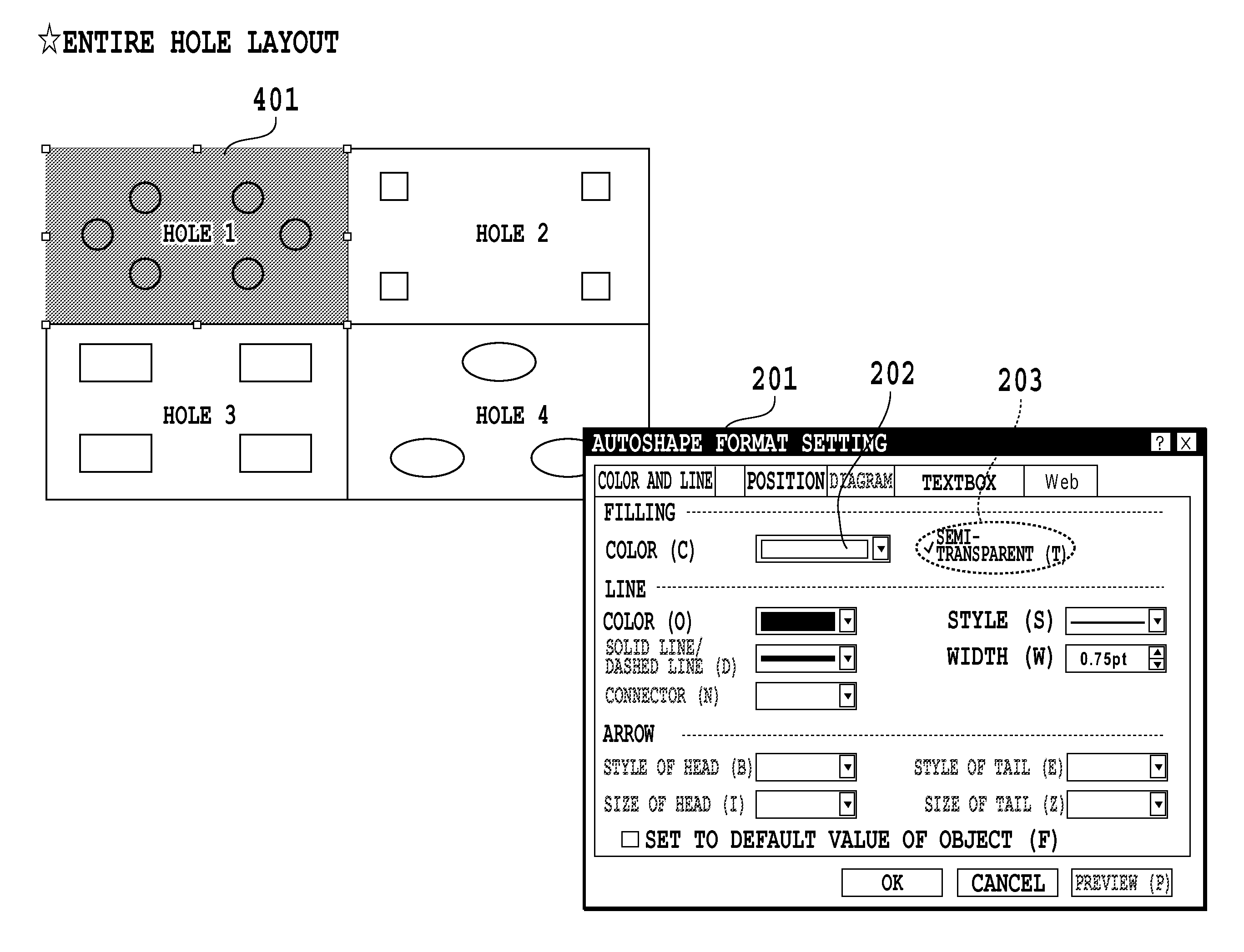
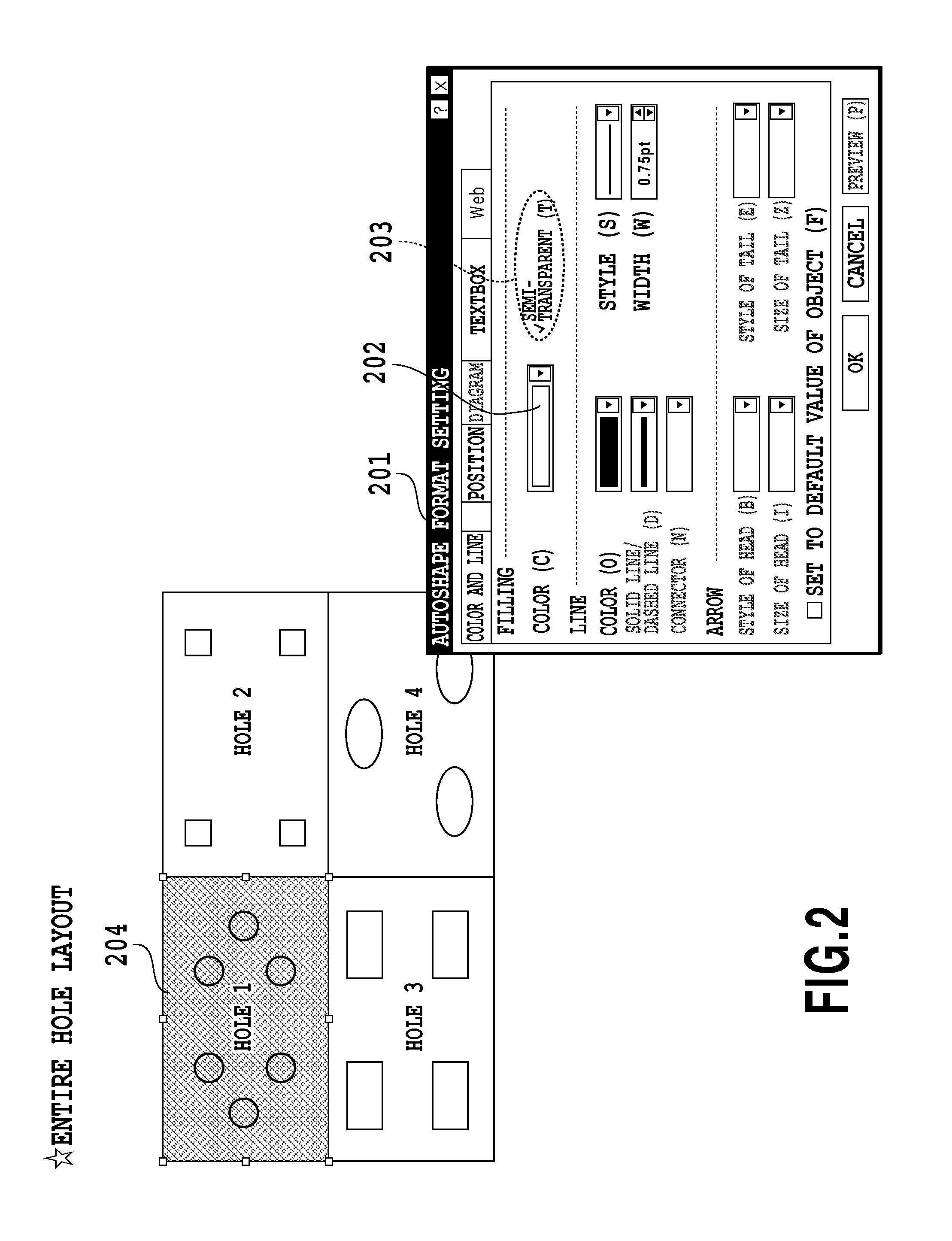
[0065]In this case, the user can specify the semi-transparency format using the GUI 201 shown in FIG. 2. If, for example, the user specifies semi-transparency by the filling-color specification 202 and the semi-transparency specification 203, the CPU 11 defines the PDL data of the image specified above as the PDL data to be rendered semi-transparent. The CPU 11 also reads out a semi-transparent object (PDL data) which is a predefined filling pattern suc...

second embodiment

[0102]Although the first embodiment allows the user to determine the pattern density adjustment by displaying the image after screen processing, an example of automating the above-mentioned user's determination will be described with the present embodiment using the flow chart of FIG. 19. Here, for each step of FIG. 19, like reference numerals are assigned to the steps similar to those in FIG. 10 and a detailed description thereof is omitted.

[0103]First, in step 1901, the CPU 11 executes default setting of the initial value of the adjusted color value. Specifically, an unadjusted state is provided by setting the adjusted color value equal to 0. The CPU 11 stores the adjusted color value in the RAM 13.

[0104]Next, in step 1002, the CPU 11 analyzes the PDL data to be defined as image data for printing with regard to whether or not a semi-transparent object is included in the PDL data created by an application as shown in FIG. 2. Specifically, as described in the first embodiment, extra...

third embodiment

[0131]Although the first embodiment described an example of letting the user determine the pattern density adjustment and the second embodiment described an example of automating the user's determination, the present embodiment describes, using the flow chart of FIG. 20, an example of displaying a warning and letting the user perform correction in a semiautomatic manner.

[0132]First, in step 1901, the CPU 11 executes default setting of the initial value of the adjusted color value. Specifically, an unadjusted state is provided by setting the adjusted color value equal to 0.

[0133]Next, in step 1002, the CPU 11 analyzes the PDL data to be defined as image data for printing with regard to whether or not a semi-transparent object is included in the PDL data created by an application as shown in FIG. 2. Specifically, the semi-transparent object of the object 301 shown in FIG. 3 is extracted. However, if there is no semi-transparent object, the process is simply terminated.

[0134]When a sem...


PUM


Abstract

An image processor and an image processing method which can minimize variation of color tone or density in an image after screen processing, even if semi-transparency has been specified. The image processor generates semi-transparent image data by overlaying a semi-transparent object on the PDL data to be rendered semi-transparent. Subsequently, screen processing is performed on the semi-transparent image data, by dither processing. Subsequently it is determined whether or not to define the screen processed semi-transparent image data as the image data for printing. If the result of determination is No, the halftone value of the semi-transparent object is modified to be larger than the current value.

Description

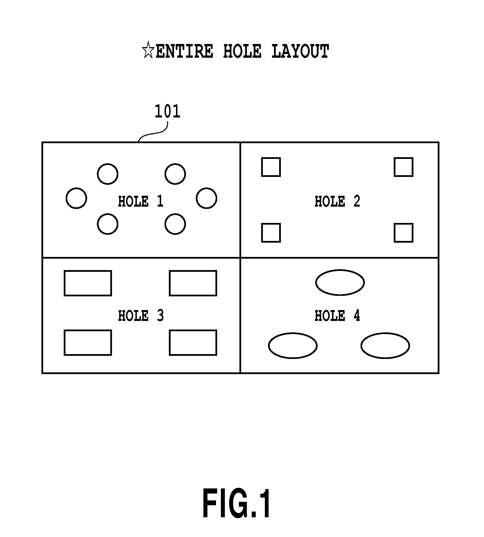
BACKGROUND OF THE INVENTION[0001]1. Field of the Invention[0002]The present invention relates to an image processor and an image processing method, and more particularly, to an image processor and an image processing method for optimally processing drawing data on a personal computer or the like.[0003]2. Description of the Related Art[0004]Recently, languages used for a page description have made it possible to specify transparency, from applications or the OS (Operation System), as an expression of overlaid objects in such a manner that an object drawn below is transparently visible. The above-mentioned language for page description will be hereafter referred to as PDL (Page Description Language).[0005]Specification of transparency is meant to specify that an overlying object is rendered transparent so that an underlying object can be seen through the overlying object.[0006]However, there may be a situation that, depending on the type of PDL, transparency specification commands are...

Claims


Application Information

Patent Timeline
Patent Type & Authority Patents(United States)
IPC IPC(8): G06K15/00G06K9/20G06F17/00G09G5/02H04N1/46G06K9/60
CPCH04N1/405H04N1/60H04N1/4053
Inventor YABE, TAKASHI
Owner CANON KK
Learn More