Control apparatus and control method of a vehicle

a control apparatus and vehicle technology, applied in the direction of process and machine control, brake systems, instruments, etc., can solve the problem of limited change amount of estimated road surface gradient, and achieve the effect of suppressing downhill sliding of the vehicl

Active Publication Date: 2012-04-17
TOYOTA JIDOSHA KK
View PDF12 Cites 4 Cited by
  • Summary
  • Abstract
  • Description
  • Claims
  • Application Information

AI Technical Summary

Benefits of technology

[0008]It is an object of this invention to provide a control apparatus and control method of a vehicle which suppresses downhill sliding of a vehicle on an upward slope.
[0010]According to the first aspect, the estimating portion limits a change amount of the estimated road surface gradient when a current vehicle speed is equal to or below a lower limit value of an absolute value of a vehicle speed corresponding to the rotation speed which can be detected by the rotation speed detecting device. As a result, the change amount of the estimated road surface gradient is limited even when the derivative value of the rotation speed abruptly changes when the vehicle speed reaches several km / h after the vehicle starts to move. Therefore, an abrupt change in the estimated road surface gradient can be suppressed. Accordingly, for example, in a vehicle that is stopped on an upward slope, an abrupt change in the estimated road surface gradient can be suppressed when the driver releases the brake pedal and the vehicle starts to move. That is, on an upward slope, an abrupt decrease in the estimated road surface gradient can be suppressed. As a result, the creep torque can be increased appropriately according to the road surface gradient, which makes it possible to suppress the vehicle from sliding downhill backwards and thus minimize the unpleasant sensation imparted on the driver. Hence, a control apparatus of a vehicle that suppresses downhill sliding of a vehicle on an upward slope can be provided.
[0012]According to this structure, the estimating portion limits the change amount to equal to or below a predetermined change amount. As a result, the change amount of the estimated road surface gradient is limited to equal to or below the predetermined change amount even when the derivative value of the rotation speed abruptly changes when the vehicle speed reaches several km / h after the vehicle starts to move. Therefore, an abrupt change in the estimated road surface gradient can be suppressed. As a result, on an upward slope, the creep torque can be increased appropriately according to the road surface gradient, which makes it possible to suppress the vehicle from sliding downhill backwards.
[0014]According to this structure, the estimating portion estimates the road surface gradient by correcting it based on the detected acceleration when the detected acceleration is not within a predetermined range corresponding to the estimated road surface gradient. Therefore, it can be determined that the estimated road surface gradient is changing abruptly, i.e., that the derivative value of the rotation speed is changing abruptly, when the acceleration detected by the acceleration detecting device is not within a predetermined range that corresponds to the estimated road surface gradient. Accordingly, estimating the road surface gradient by appropriately correcting the road surface gradient based on the detected acceleration enables an abrupt change in the creep torque to be suppressed. Thus, for example, in a vehicle that is stopped on an upward slope, an abrupt change in the estimated road surface gradient can be suppressed when the driver releases the brake pedal and the vehicle starts to move. That is, on an upward slope, an abrupt decrease in the estimated road surface gradient can be suppressed. As a result, the creep torque can be increased appropriately according to the road surface gradient so the vehicle can be suppressed from sliding downhill backwards. Accordingly, the unpleasant sensation imparted on the driver from the vehicle sliding backwards can be minimized. Thus, a control apparatus of a vehicle that suppresses downhill sliding of a vehicle on an upward slope can be provided.
[0016]According to this structure, the control apparatus controls the motor according to the estimated road surface gradient. Therefore, a vehicle on an upwards slope can be suppressed from sliding downhill because creep torque according to the estimated road surface gradient can be output.

Problems solved by technology

As a result, the change amount of the estimated road surface gradient is limited even when the derivative value of the rotation speed abruptly changes when the vehicle speed reaches several km / h after the vehicle starts to move.

Method used


Image

  • Control apparatus and control method of a vehicle
  • Control apparatus and control method of a vehicle
  • Control apparatus and control method of a vehicle

Examples


Embodiment Construction

[0035]Hereinafter, embodiments of the invention will be described in detail with reference to the accompanying drawings. In the following description, like parts with be denoted by like reference numerals. Like parts will also be referred to by same nomenclature and will have the same function. Therefore, detailed descriptions of those parts will not be repeated.

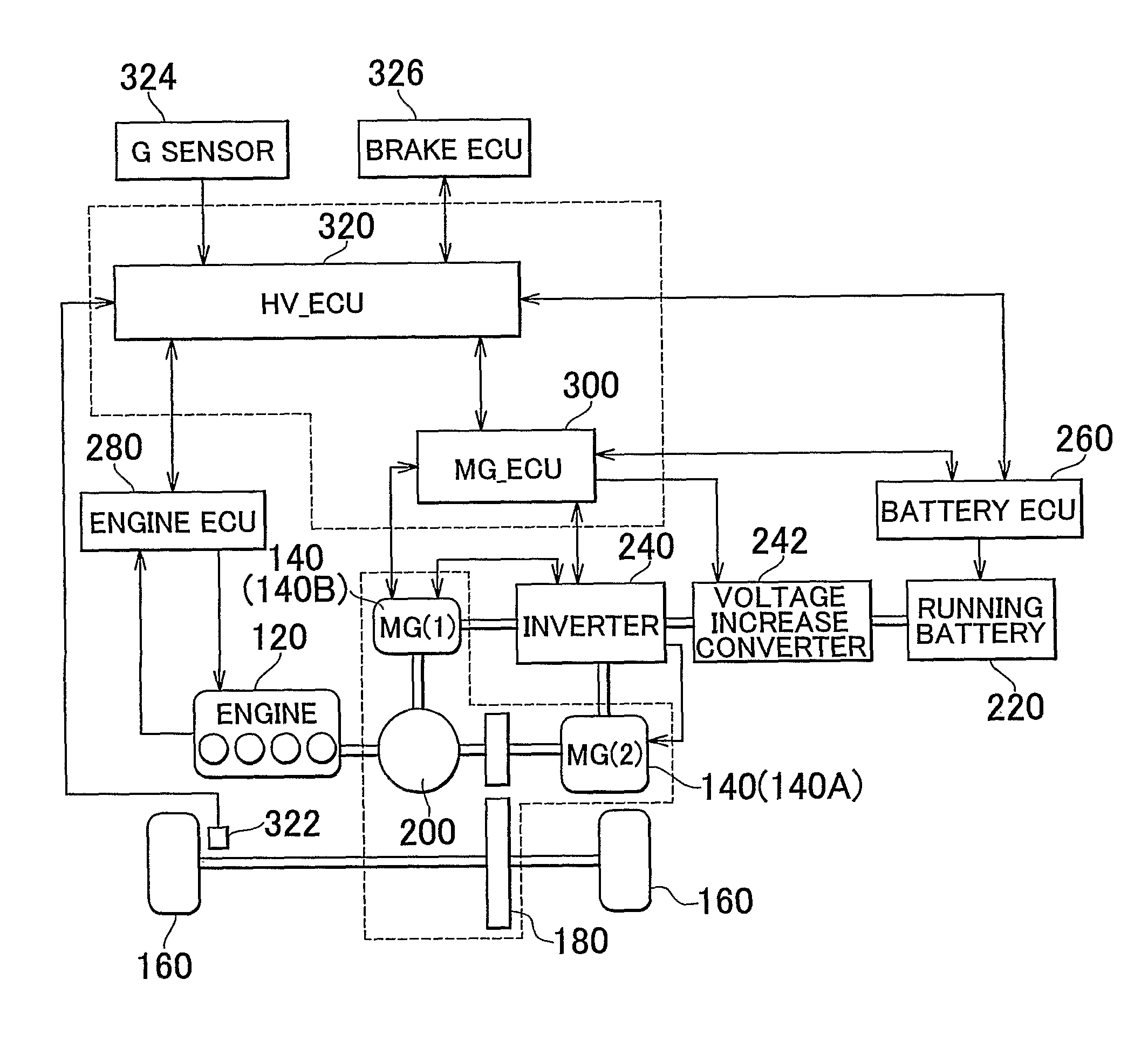
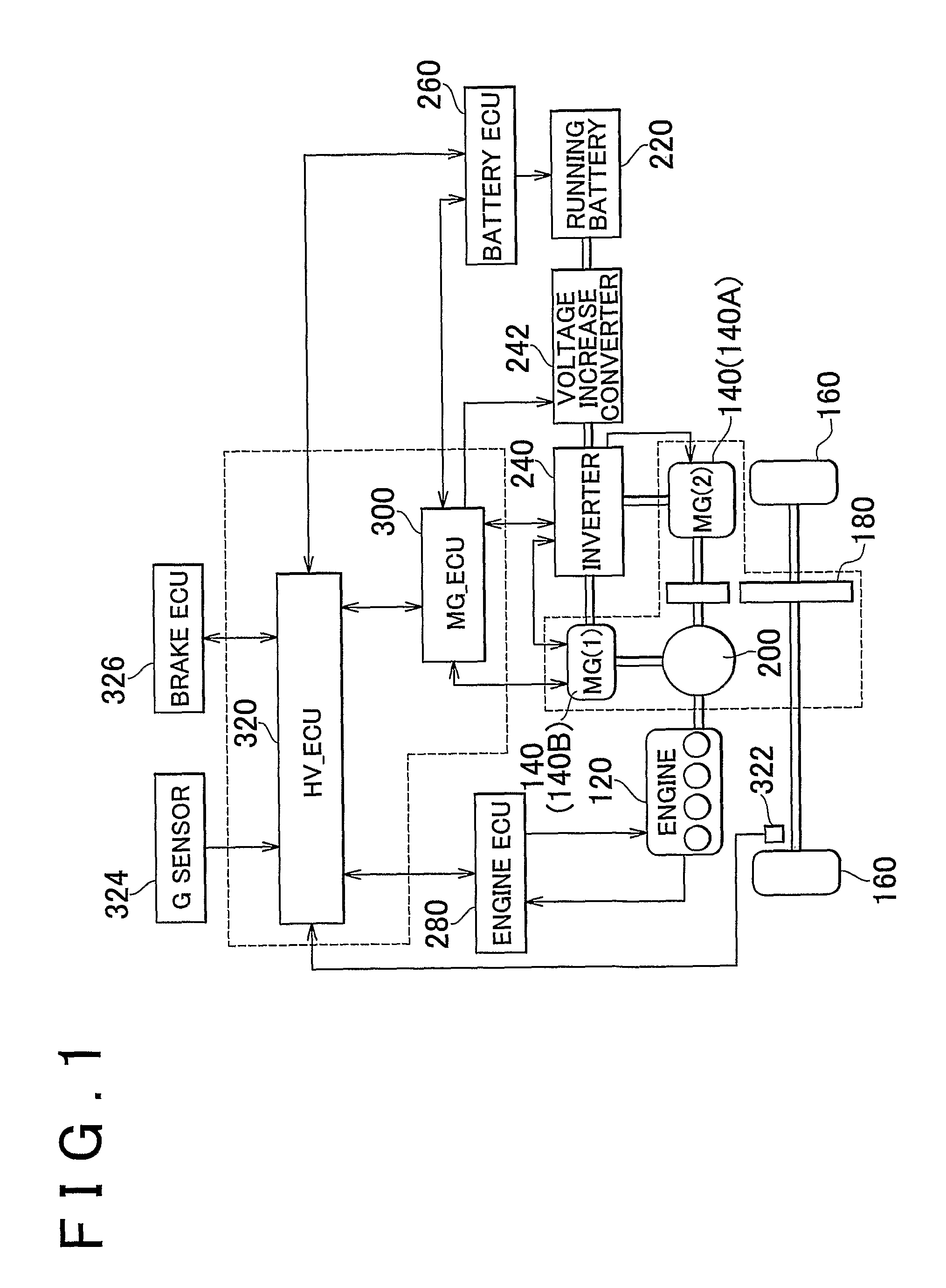
[0036]A control block diagram of a hybrid vehicle according to a first embodiment of the invention will now be described with reference to FIG. 1. It should be noted, however, that the invention is not limited to the hybrid vehicle shown in FIG. 1 as long as a motor-generator which serves as a driving source is coupled to driven wheels. The hybrid vehicle may also take another form having a secondary battery. Also, an electricity storing mechanism such as a capacitor may be provided instead of the secondary battery. In addition, when the secondary battery is provided, it may be a nickel-metal hydride battery or a lithium-ion...


PUM


Abstract

An HV_ECU executes a program including a step of calculating an estimated gradient, a step of performing rate limit processing on a change in the estimated gradient when on a hill and an absolute value of the vehicle speed is equal to or below V(0), a step of performing hysteresis processing, a step of calculating a creep increase coefficient, and a step of calculating a creep increase torque.

Description

BACKGROUND OF THE INVENTION[0001]1. Field of the Invention[0002]The invention relates to a control apparatus and a control method of a vehicle. More particularly, the invention relates to a control apparatus and a control method of a vehicle which uses a motor as a driving source.[0003]2. Description of the Related Art[0004]In recent years, vehicles which run by the driving force generated by a motor such as hybrid vehicles, fuel cell vehicles, and electric vehicles have been the focus of much attention as one measure to combat environmental problems. In these kinds of vehicles, technology is known for generating creep torque using the motor in order to prevent the vehicle from moving backwards when taking off from a standstill or when stopped on an upward slope, for example.[0005]Japanese Application Publication No. JP-A-2005-33866, for example, describes a control apparatus of a hybrid vehicle that prevents brake drag when the vehicle takes off from a standstill, while also preven...

Claims


Application Information

Patent Timeline
Patent Type & Authority Patents(United States)
IPC IPC(8): B60T8/32B60V1/00G06F7/70B60K6/445B60L9/18B60L15/20
CPCB60W30/18063B60W40/072B60W40/076B60K6/445B60W10/04B60W10/06B60W10/08B60W10/12B60W10/18B60W30/18B60W2520/10B60W2520/105B60W2550/142B60W2720/28Y02T10/6286Y02T10/7258Y02T10/6239B60W2552/15Y02T10/62Y02T10/72B60W30/188
Inventor AMAMIYA, SUMIKOMUTA, KOICHIROKITAMURA, YUICHIRO
Owner TOYOTA JIDOSHA KK
Why Eureka
Try Eureka