
Image signal processing device and image signal processing method, and computer program

a signal processing and image technology, applied in the field of image signal processing devices and image signal processing methods, can solve the problems of eye strain or dizziness, strain or discomfort, and difficulty in fusion of left and right images, and achieve the effect of optimal stereoscopic

Inactive Publication Date: 2011-12-08
SONY CORP
View PDF3 Cites 0 Cited by
  • Summary
  • Abstract
  • Description
  • Claims
  • Application Information

AI Technical Summary

Benefits of technology

[0005]It is desirable to provide an excellent image signal processing device and an image signal processing method, and a computer program, that are able to realize an optimal stereoscopic effect by adjusting an amount of binocular parallax.
[0006]It is further desirable to provide an excellent image signal processing device and an image signal processing method, and a computer program, that are able to realize an optimal stereoscopic effect by enlargement-processing or reduction-processing a stereoscopic image and changing the amount of binocular parallax, while not causing eye strain or dizziness.

Problems solved by technology

However, if the binocular parallax is too great, fusion of the left and right images becomes difficult, and eye strain or dizziness may be caused.
Further, when software with a large amount of projection from the screen frame or with a strong stereoscopic effect is viewed, straining or discomfort may be caused.

Method used


Image

  • Image signal processing device and image signal processing method, and computer program
  • Image signal processing device and image signal processing method, and computer program
  • Image signal processing device and image signal processing method, and computer program

Examples


Embodiment Construction

[0026]Hereinbelow, embodiments of the disclosure will be described in detail referring to the drawings.

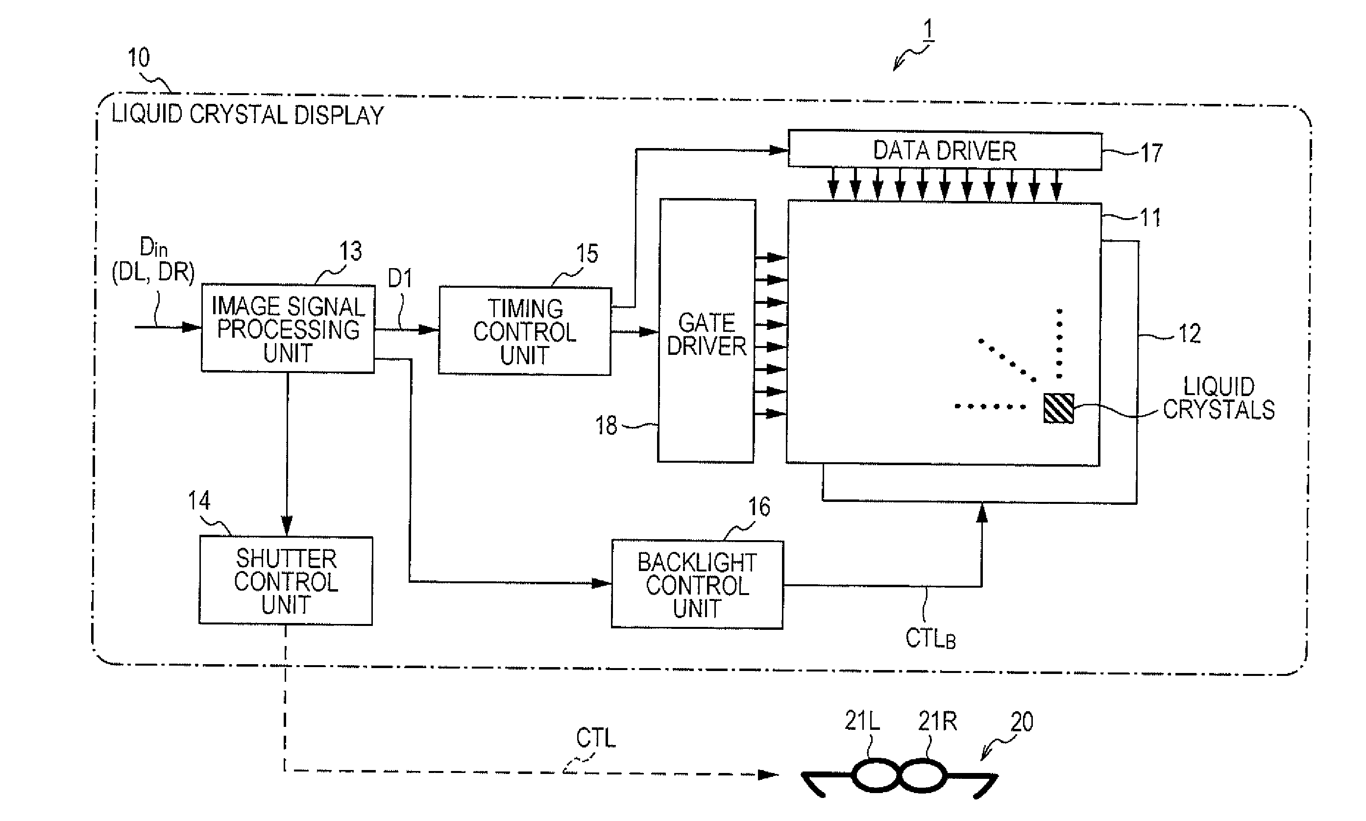
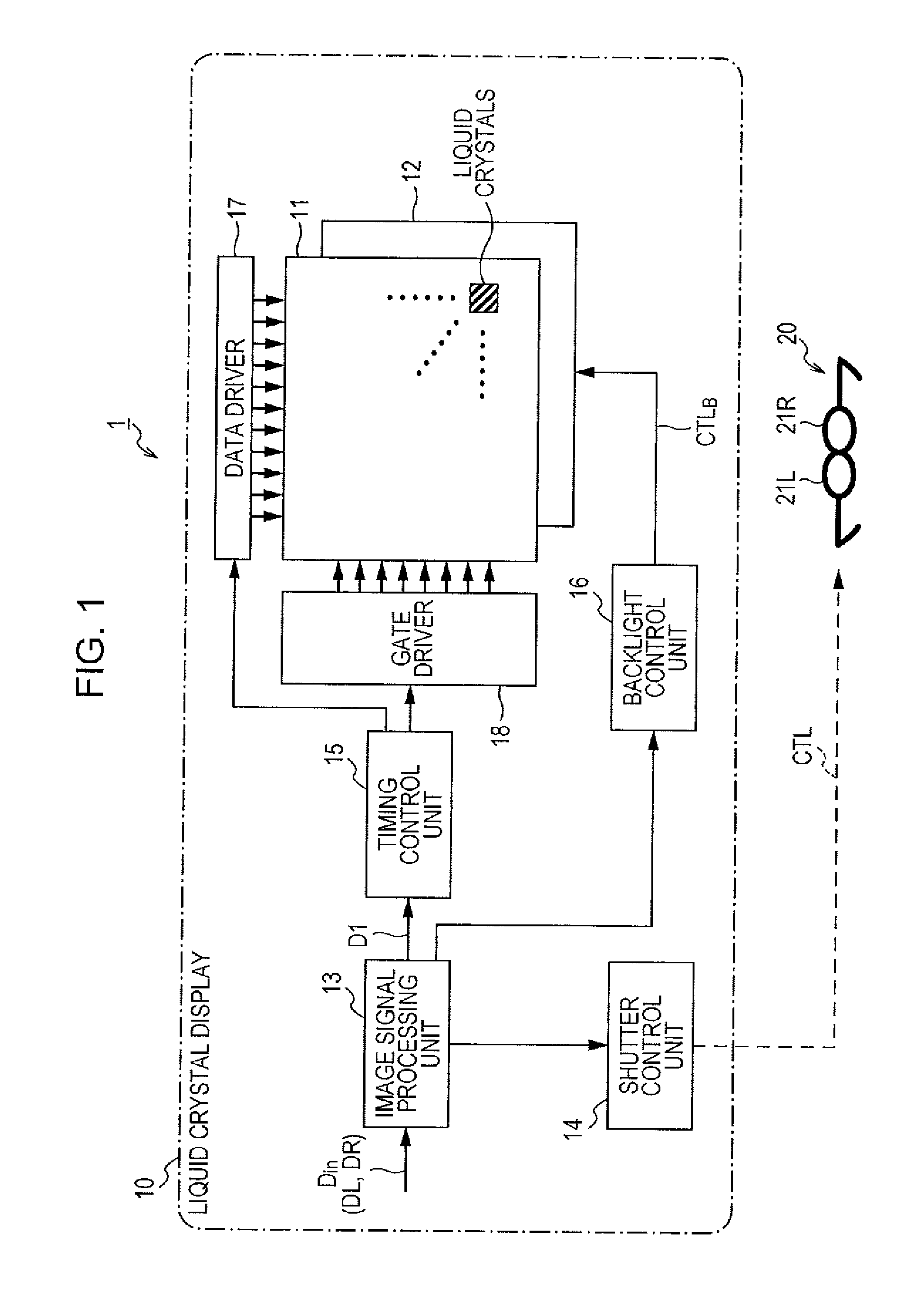
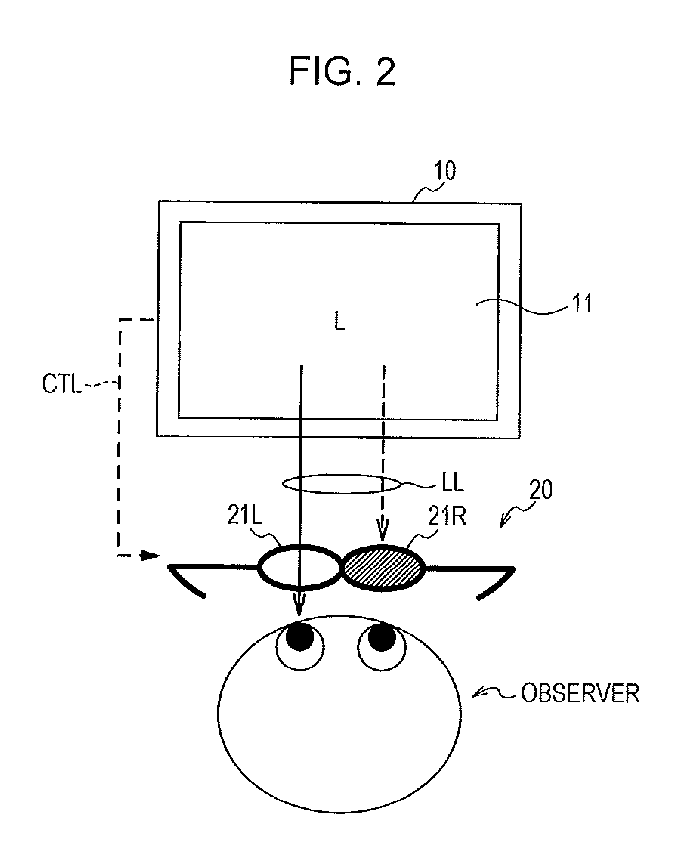
[0027]In FIG. 1 is schematically illustrated a configuration of a stereoscopic image display system 1 that is able to apply the disclosure. The stereoscopic image display system 1 shown in the diagram includes a liquid crystal display 10 that alternately screen displays a left eye image L and a right eye image R in extremely short cycles, and shutter glasses 20 that an observer wears on the head.

[0028]The liquid crystal display 10 is provided with a liquid crystal display panel 11, a backlight 12, an image signal processing unit 13, a shutter control unit 14 that controls an opening and closing timing of a shutter mechanism of the shutter glasses 20, a timing control unit 15, a backlight control unit 16, a data driver 17, and a gate driver 18. In the embodiment, the liquid crystal display 10 displays an image based on an input image signal Din that includes a right eye image signal...


PUM


Abstract

An image signal processing device including: a central area control processing unit that enlarges or reduces a central image segment of a stereoscopic image signal by a magnification factor according to a desired stereoscopic effect; a surrounding area control processing unit that reduction-processes a surrounding image segment of the stereoscopic image signal by a corresponding magnification factor when the central area control processing unit enlarges the central image segment, and enlargement-processes a surrounding image segment of the stereoscopic image signal by a corresponding magnification factor when the central area control processing unit reduces the central image segment; and a transition area control processing unit that performs, in an image segment that transitions between the central image segment and the surrounding image segment, a process of connecting a gap between the enlargement and reduction factors of the central image segment and the surrounding image segment using non-linear scaling.

Description

BACKGROUND OF THE INVENTION[0001]The present disclosure relates to an image signal processing device and an image signal processing method, and a computer program processing a stereoscopic image including a left eye image signal and a right eye image signal, and in particular, to an image signal processing device and an image signal processing method, and a computer program realizing an optimal stereoscopic effect by adjusting the amount of binocular parallax.[0002]By displaying an image having parallax between the left and right eyes, it is possible to present a stereoscopic image that appears stereoscopic to an observer. As one method of presenting a stereoscopic image, there is a method of presenting an image with parallax to both eyes by making an observer wear glasses having special optical properties. For example, a time sharing stereoscopic image display system includes a combination of a display device displaying a plurality of images each different from one another in a tim...

Claims


Application Information

Patent Timeline
IPC IPC(8): G06T15/00
CPCG03B35/16H04N13/0022H04N13/0438H04N13/0033H04N13/0029H04N13/341H04N13/144H04N13/128H04N13/139H04N13/00
Inventor HARADA, SHIGERU
Owner SONY CORP
Learn More