
Interleaving parity bits into user bits to guarantee run-length constraint

a parity bit and run-length technology, applied in the field of interleaving parity bits into user bits to guarantee run-length constraints, can solve problems such as the risk of forward error correction failure from line coding error propagation

Active Publication Date: 2012-04-17
SK HYNIX MEMORY SOLUTIONS
View PDF6 Cites 16 Cited by
  • Summary
  • Abstract
  • Description
  • Claims
  • Application Information

AI Technical Summary

Problems solved by technology

When high rate line codes are used, there is a risk of forward error correction failure from line coding error propagation.

Method used


Image

  • Interleaving parity bits into user bits to guarantee run-length constraint
  • Interleaving parity bits into user bits to guarantee run-length constraint
  • Interleaving parity bits into user bits to guarantee run-length constraint

Examples


Embodiment Construction

[0008]The invention can be implemented in numerous ways, including as a process, an apparatus, a system, a composition of matter, a computer readable medium such as a computer readable storage medium or a computer network wherein program instructions are sent over optical or communication links. In this specification, these implementations, or any other form that the invention may take, may be referred to as techniques. A component such as a processor or a memory described as being configured to perform a task includes both a general component that is temporarily configured to perform the task at a given time or a specific component that is manufactured to perform the task. In general, the order of the steps of disclosed processes may be altered within the scope of the invention.

[0009]A detailed description of one or more embodiments of the invention is provided below along with accompanying figures that illustrate the principles of the invention. The invention is described in conne...


PUM


Abstract

A method of satisfying a specified run length constraint is disclosed. A systematically error correction encoded sequence of received symbols is received, wherein the received symbols include data symbols and parity symbols. The parity symbols are interleaved with the data symbols to produce interleaved symbols that satisfy the specified run length constraint.

Description

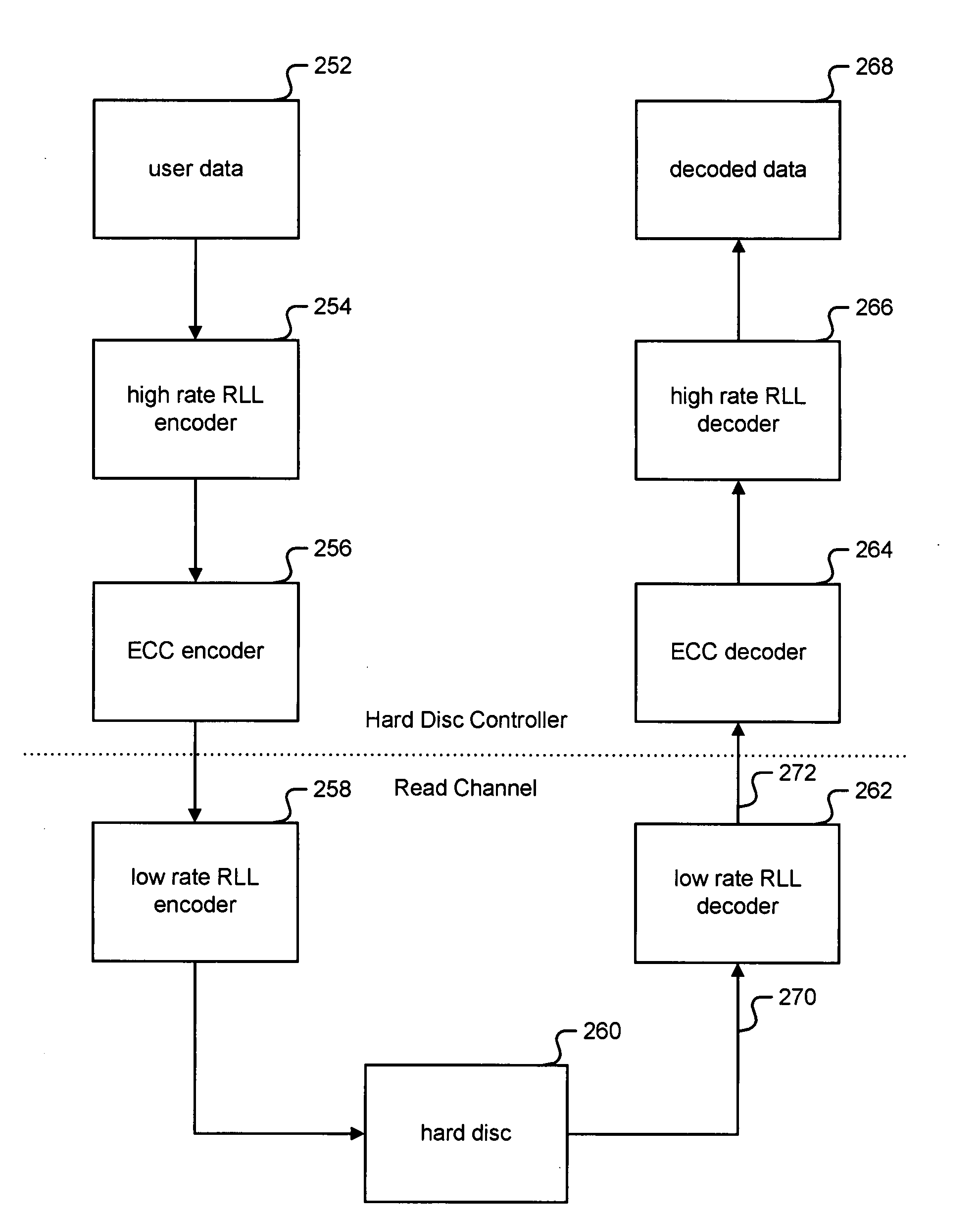
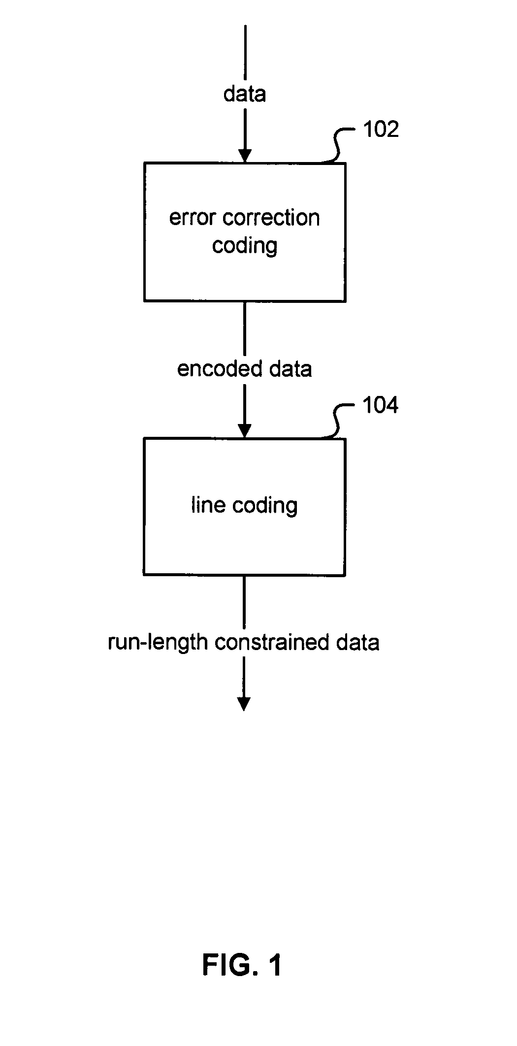
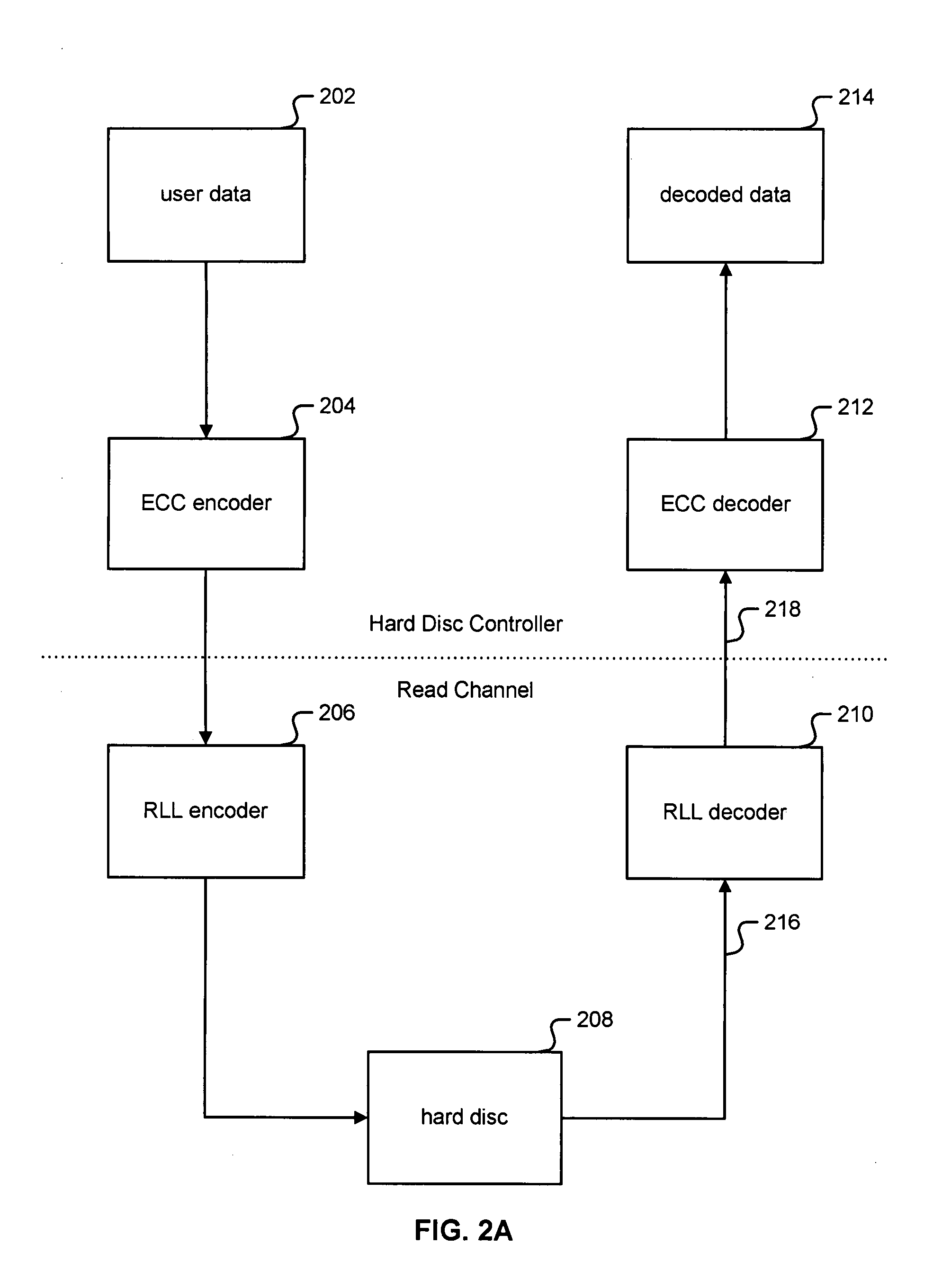
BACKGROUND OF THE INVENTION[0001]Forward error correction and line coding are used together in digital communications and storage technologies. These technologies find wide application, including disc drives, where high rate line codes are used. When high rate line codes are used, there is a risk of forward error correction failure from line coding error propagation. Therefore, there exists a need for a system to reduce or eliminate the risk of forward error correction failure from line coding error propagation.BRIEF DESCRIPTION OF THE DRAWINGS[0002]Various embodiments of the invention are disclosed in the following detailed description and the accompanying drawings.[0003]FIG. 1 is a block diagram illustrating an embodiment of an encoding process.[0004]FIG. 2A is a block diagram illustrating an example of a technique for error correction coding coupled with line coding in a hard disc drive system.[0005]FIG. 2B is a block diagram illustrating an example of a reverse coding technique ...

Claims


Application Information

Patent Timeline
IPC IPC(8): G11B20/14H03M13/29H03M7/46G11B20/18
CPCG11B20/1426G11B20/1833H03M7/46H03M13/27H03M13/6343G11B20/1866G11B2020/185G11B2220/2516H03M13/1102H03M13/1515H03M5/145
Inventor KOU, YU
Owner SK HYNIX MEMORY SOLUTIONS
Learn More