Layered transmission apparatus and method, reception apparatus, and reception method

a transmission apparatus and transmission method technology, applied in the direction of digital transmission, electrical apparatus, pulse technique, etc., can solve the problems of inter-layer interference, possible drastic degraded reception performance, reduced coverage, etc., and achieve the effect of increasing the number of layers which can be simultaneously transmitted and reducing inter-layer interferen

Inactive Publication Date: 2011-08-11
ELECTRONICS & TELECOMM RES INST
View PDF45 Cites 7 Cited by
  • Summary
  • Abstract
  • Description
  • Claims
  • Application Information

AI Technical Summary

Benefits of technology

[0026]According to an embodiment of the present invention, the number of layers which can be simultaneously transmitted can be increased, and because symbol metrics of all the layers are simultaneously estimated from a received signal and decoding is performed by layer, interlayer interference can be reduced.

Problems solved by technology

Thus, in order for the transmitter to transmit more layers, a modulation order must be increased; however, in this case, the coverage is reduced and reception performance is possibly drastically degraded.
In addition, the reception apparatus hitherto performs demodulation by layer, causing inter-layer interference.
So, in order to solve this problem, if the transmitter assigns more transmission power to the base layer than that to the enhancement layer to reduce inter-layer interference, the distance between constellation points of the enhancement layer would become narrow, making it difficult to transmit two or more layers.

Method used


Image

  • Layered transmission apparatus and method, reception apparatus, and reception method
  • Layered transmission apparatus and method, reception apparatus, and reception method
  • Layered transmission apparatus and method, reception apparatus, and reception method

Examples


Embodiment Construction

[0031]In the following detailed description, only certain exemplary embodiments of the present invention have been shown and described, simply by way of illustration. As those skilled in the art would realize, the described embodiments may be modified in various different ways, all without departing from the spirit or scope of the present invention. Accordingly, the drawings and description are to be regarded as illustrative in nature and not restrictive. Like reference numerals designate like elements throughout the specification.

[0032]Throughout the specification, unless explicitly described to the contrary, the word “comprise” and variations such as “comprises” or “comprising”, will be understood to imply the inclusion of stated elements but not the exclusion of any other elements.

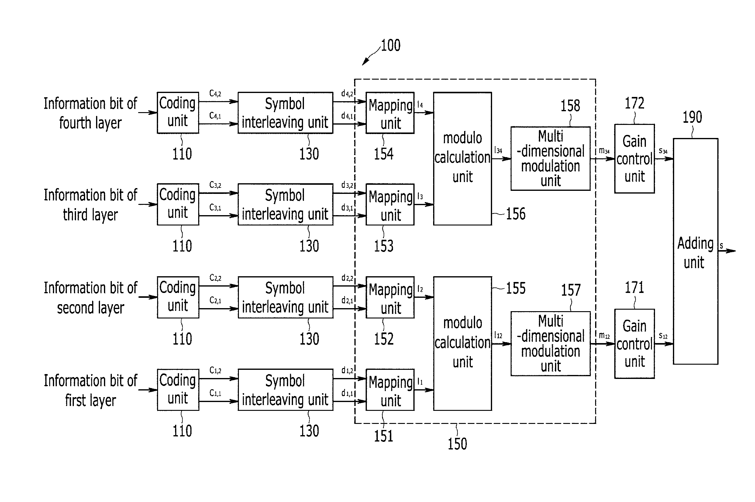
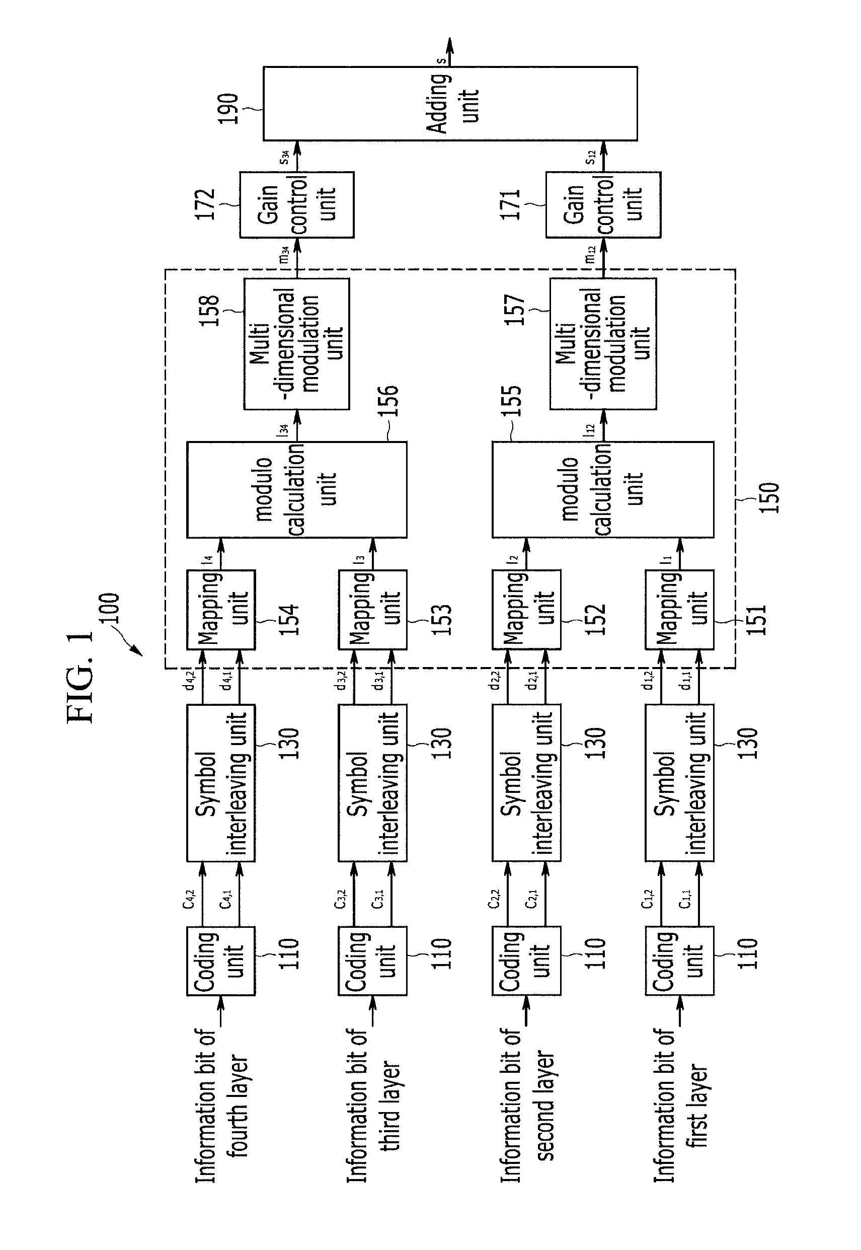
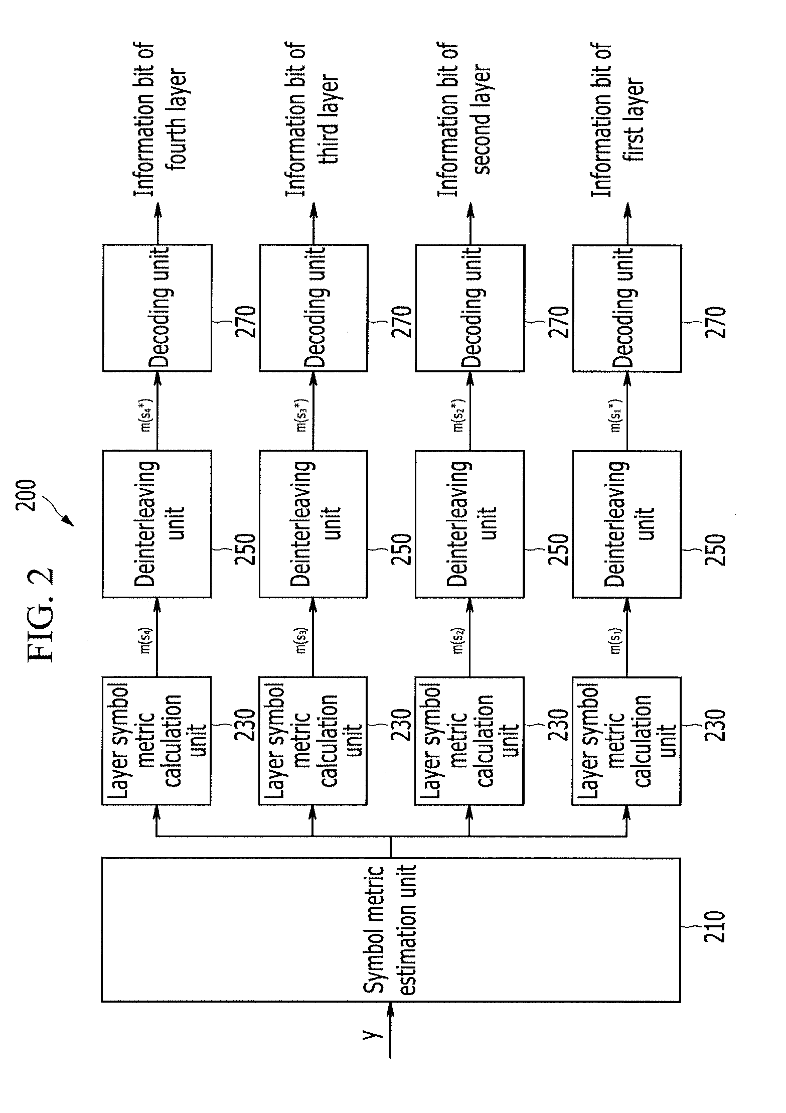
[0033]A layered transmission apparatus and method, a reception apparatus, and a reception method according to exemplary embodiments of the present invention will now be described with reference to the a...


PUM


Abstract

A layered transmission apparatus for transmitting information regarding a plurality of layers includes: a plurality of coding units, which correspond to each of the plurality of layers, configured to code an information bit of a corresponding layer to generate code bits; a plurality of symbol interleaving units, which correspond to each of the plurality of coding units, configured to symbol-interleave the code bit of a corresponding coding unit to generate an interleaved symbol; a modulation unit configured to classify the plurality of layers into a plurality of layer groups, and modulate the interleaved symbol corresponding to each of the layer groups to generate a modulation symbol of each of the layer groups; a gain control unit configured to control the gain of the modulation symbol of each of the layer groups; and an adding unit configured to add the gain-controlled modulation symbols of the plurality of layer groups to generate a transmission symbol.

Description

CROSS-REFERENCE TO RELATED APPLICATION[0001]This application claims priority to and the benefit of Korean Patent Application No. 10-2010-0012700, 10-2010-0027931, 10-2010-0027929, 10-2010-0027928 and 10-2011-0011883 filed in the Korean Intellectual Property Office on Feb. 11, 2010, Mar. 29, 2010, Mar. 29, 2010, Mar. 29, 2010 and Feb. 10, 2011, the entire contents of which are incorporated herein by reference.BACKGROUND OF THE INVENTION[0002](a) Field of the Invention[0003]The present invention relates to a layered transmission apparatus and method, a reception apparatus, and a reception method.[0004](b) Description of the Related Art[0005]A broadcasting system, providing diverse video qualities, transmits scalable video coded image information so as to be compatible with reception apparatuses having various performances. A scalable video coding (SVC) is classifying information into a plurality of layers according to the significance of image information and transmitting the same. Wh...

Claims


Application Information

Patent Timeline
Patent Type & Authority Applications(United States)
IPC IPC(8): H04L27/00
CPCH04L27/3488
Inventor KIM, SEONG RAGWON, SEUCK HOKIM, JUNG-IM
Owner ELECTRONICS & TELECOMM RES INST
Why Eureka
Try Eureka