Eureka AIR delivers breakthrough ideas for toughest innovation challenges, trusted by R&D personnel around the world.

Heating apparatus, heating method, coating apparatus, and storage medium

a technology of heating method and heating method, which is applied in the direction of muffle furnace, oven, oven, etc., can solve the problems of reducing product yield and the inability to increase the number of layers, and achieve the effect of reducing operation time and small heigh

Inactive Publication Date: 2007-08-23
TOKYO ELECTRON LTD
View PDF2 Cites 10 Cited by
  • Summary
  • Abstract
  • Description
  • Claims
  • Application Information

AI Technical Summary

Benefits of technology

[0014]The present invention was made in view of such circumstances. An object of the present invention is to provide a heating apparatus cooling a substrate heated by a hot plate at a cooling position (for example, a cooling plate) adjacent to the hot plate, capable of achieving a smaller height and reducing an operation time in the apparatus, in which contamination of the substrate by particles or the like is less likely, a coating apparatus incorporating the heating apparatus, a heating method, and a storage medium storing a program for performing the method.
[0023]According to the present invention, the substrate is loaded onto the hot plate while it is mounted on the gap forming member provided on the wire and the heat treatment of the substrate is performed in that state. Therefore, an up / down pin and an elevator mechanism for elevating / lowering the substrate are not required, and clearance for delivery of the substrate by means of the up / down pin is not necessary either. Accordingly, the height of the heating apparatus can be suppressed. Consequently, the number of layers of the heating apparatuses installed in the coating apparatus can be increased and treatment performance can be enhanced.
[0024]In addition, an operation time required for an elevation / lowering operation of the up / down pin is not necessary, and the overhead time not directly relevant to heat treatment can correspondingly be reduced, thus improving throughput. Moreover, unlike the conventional example, as the cooling plate having a large thickness is not loaded into the heating apparatus, a ceiling portion of the heating chamber can be low and the structure without elevating / lowering the ceiling portion can be adopted. Therefore, by adopting such a structure, the height of the heating apparatus can further be made smaller, and further reduction in the overhead time can be achieved by dispensing with elevation / lowering of the ceiling portion.
[0025]Further, the substrate is mounted on the gap forming member and subjected to heat treatment in a state floating above the surface of the hot plate with a gap therefrom. Therefore, as compared with the case of transfer in such a state that the substrate is directly mounted on the wire, adhesion of particles or the like to the surface of the substrate in the heating chamber is less likely. Consequently, the surface of the substrate is not contaminated and the product yield is not lowered. Still further, delivery of the substrate between the external substrate transfer mechanism and the cooling position is performed by elevating / lowering the substrate transfer mechanism while forming a space for passage of the pulley provided at one end of the substrate transfer path between the substrate transfer mechanism and the cooling position. Therefore, the up / down pin for delivery of the substrate is not necessary either at the cooling position.

Problems solved by technology

In such a case, if the heating apparatus has a large height, the number of layers cannot be increased.
In addition, if a wafer is directly mounted on the wires, the wafer is contaminated due to adhesion of particles or the like caused by contact between the wafer and the wires, which leads to lower product yield.

Method used


Image

  • Heating apparatus, heating method, coating apparatus, and storage medium
  • Heating apparatus, heating method, coating apparatus, and storage medium
  • Heating apparatus, heating method, coating apparatus, and storage medium

Examples


Embodiment Construction

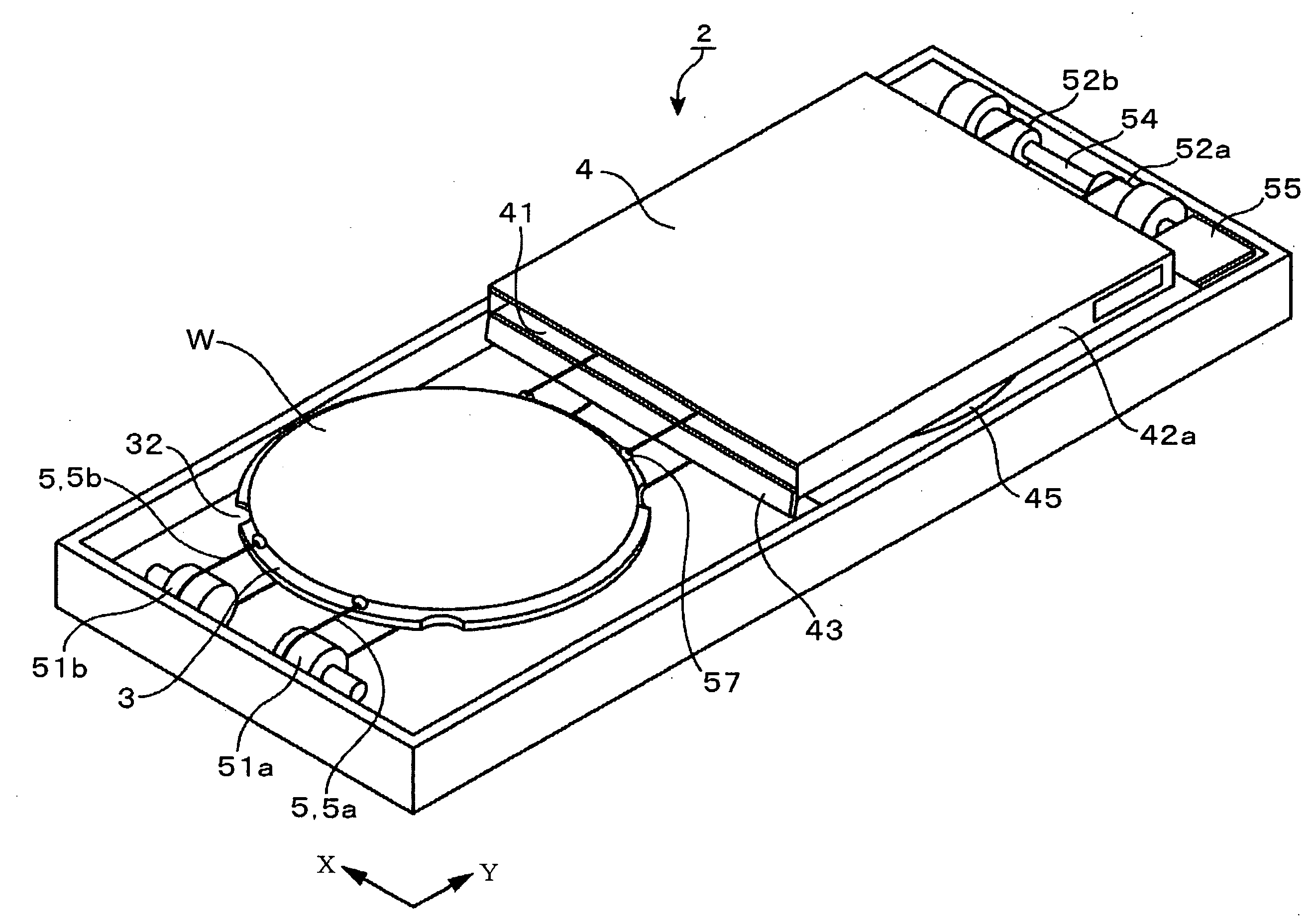
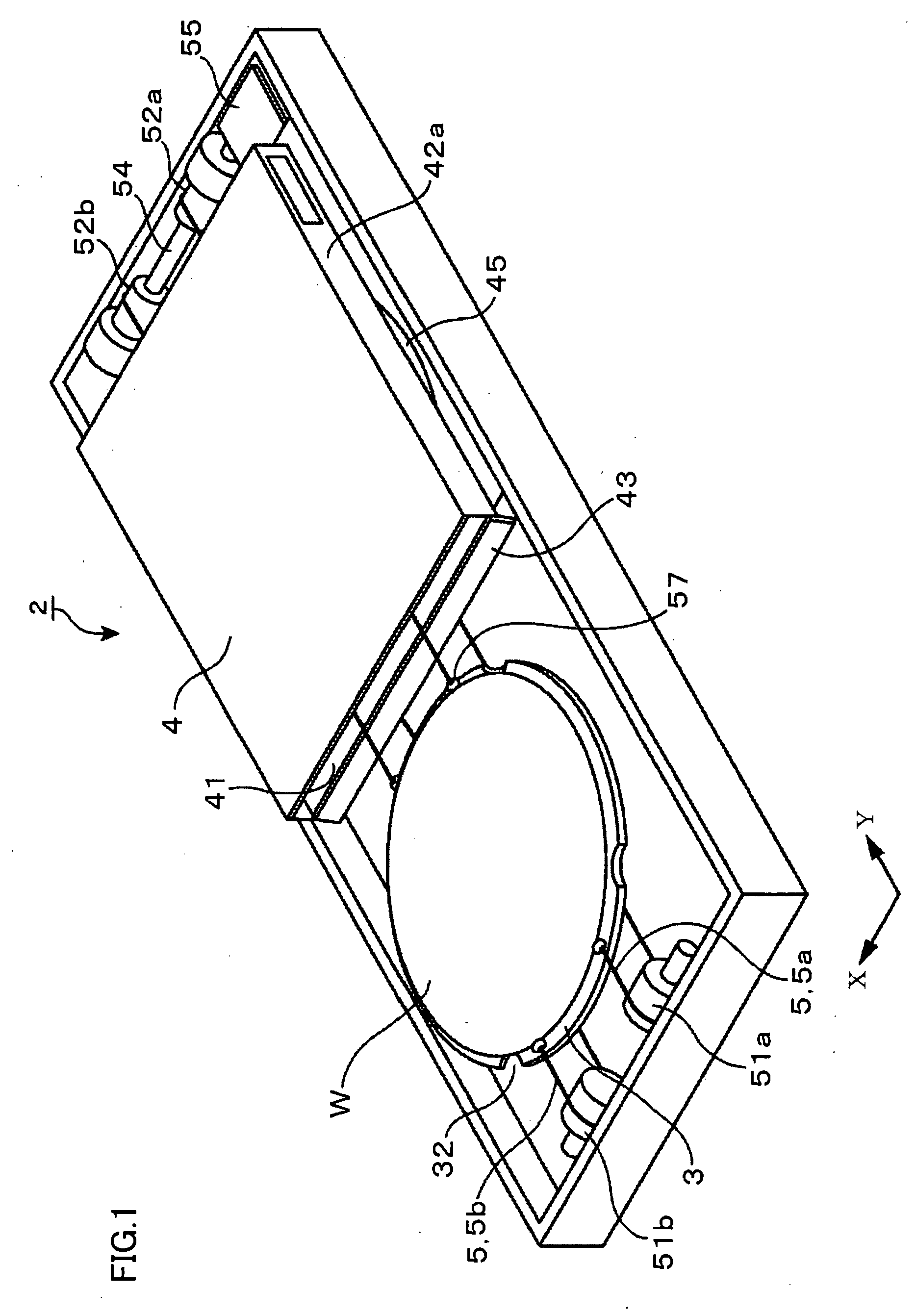
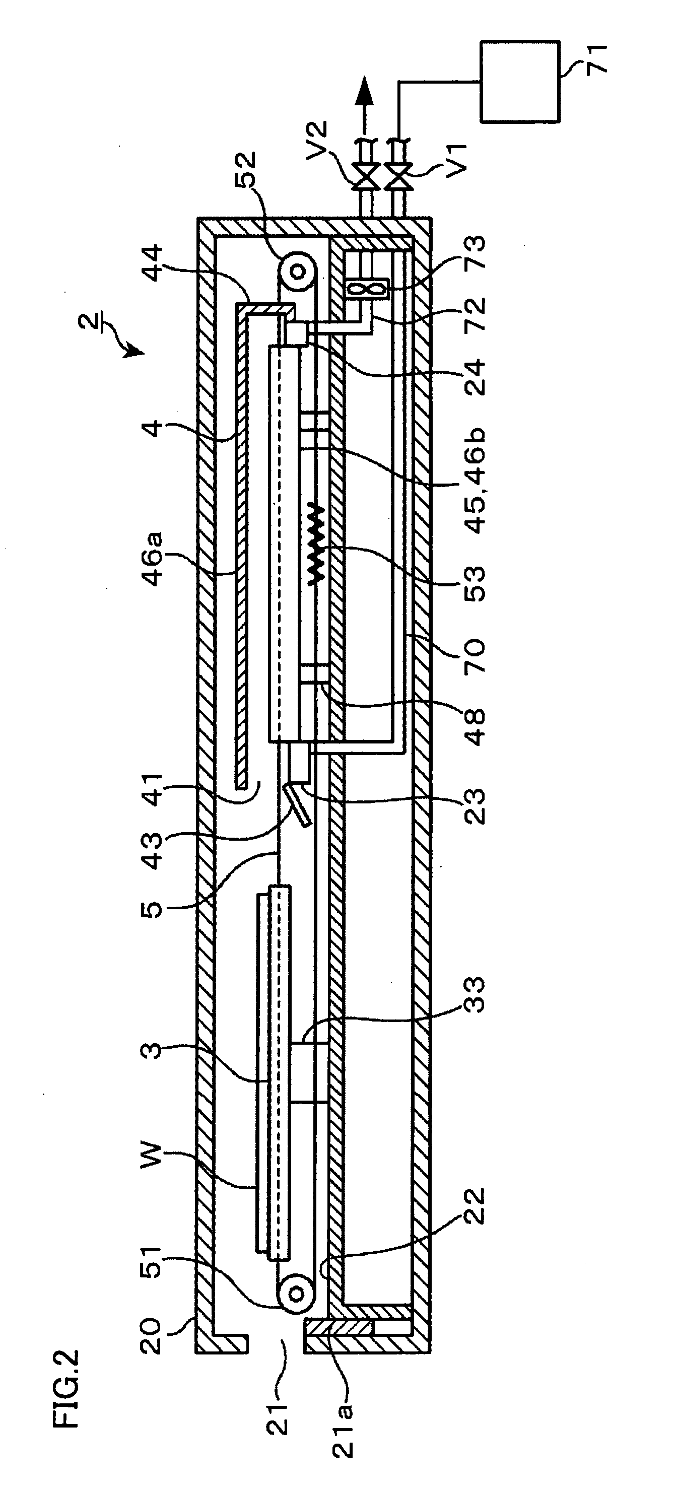
[0041]A heating apparatus 2 representing an exemplary embodiment of a heating apparatus according to the present invention, which, for example, subjects wafer W representing the substrate to heat treatment in a vapor atmosphere of a hydrophobic treatment agent to attain hydrophobicity of the surface of wafer W, will be described hereinafter with reference to FIGS. 1 to 9B. Here, for example, a 12-inch wafer W is used. As shown in FIG. 2, heating apparatus 2 includes a housing 20 serving as a treatment container, a transfer port 21 of wafer W is provided in a sidewall of housing 20, and a shutter 21a opens / closes transfer port 21. Shutter 21a is provided in order to prevent airflow formed around wafer W as will be described later from being disturbed, due to flow-in of outside air into housing 20 through transfer port 21 during heating of wafer W. In order to prevent the airflow from being disturbed, for example, an air curtain may be provided around transfer port 21 instead of shutt...


PUM

PropertyMeasurementUnit
distanceaaaaaaaaaa
temperatureaaaaaaaaaa
thicknessaaaaaaaaaa

Abstract

A heating apparatus cooling a substrate heated by a hot plate at a cooling position adjacent to the hot plate, capable of achieving a smaller height and reducing an operation time in the apparatus, in which contamination of the substrate by particles or the like is less likely, and the like, are provided. The heating apparatus includes a hot plate for heating a wafer representing a substrate from below, in a heating chamber having a wafer load / unload port. In addition, a wire for transferring the wafer between a cooling position of the substrate adjacent to the load / unload port of the heating chamber (position above a cooling plate) and a position above the hot plate is provided and extends. The wafer is mounted on a gap forming member provided on the wire, and thereafter loaded into the heating chamber.

Description

BACKGROUND OF THE INVENTION[0001]1. Field of the Invention[0002]The present invention relates to a heating apparatus for performing heat treatment by positioning a substrate on a hot plate and thereafter cooling the substrate at a cooling position adjacent to the hot plate, a heating method, and a coating apparatus using the heating apparatus, and further relates to a storage medium storing a computer program for performing the heating method.[0003]2. Description of the Background Art[0004]A coating and development apparatus applying a resist to a substrate and developing the exposed substrate has been used as an apparatus for forming a resist pattern on a semiconductor wafer (hereinafter, referred to as “wafer”) or a glass substrate for LCD (liquid crystal display) representing the substrate. In this apparatus, a hydrophobic treatment unit for subjecting the surface of the substrate to hydrophobic treatment by bringing the substrate into contact with vapor of a hydrophobic treatmen...

Claims


Application Information

Patent Timeline
Patent Type & Authority Applications(United States)
IPC IPC(8): A21B1/00
CPCH01L21/67748H01L21/67109Y10S198/952H01L21/324
Inventor HIRAKAWA, OSAMUAKIMOTO, MASAMIHAYASHI, SHINICHI
Owner TOKYO ELECTRON LTD
Why Eureka
Eureka Blog
Learn More