
Toilet tank mounted odor eliminator

a technology for odor elimination and toilets, which is applied in the field of toilet tank mounted odor elimination devices, and can solve the problem of destroying odors essentially

Inactive Publication Date: 2012-04-24
ZUCO WATER LLC
View PDF15 Cites 10 Cited by
  • Summary
  • Abstract
  • Description
  • Claims
  • Application Information

AI Technical Summary

Benefits of technology

Effectively eliminates odors and pathogens from toilet bowl gases, reducing health hazards and social discomfort by ensuring complete removal of malodorous gases and aerosols, while being safe and easy to install.

Problems solved by technology

Thereby, odors generated will be essentially destroyed.

Method used


Image

  • Toilet tank mounted odor eliminator
  • Toilet tank mounted odor eliminator
  • Toilet tank mounted odor eliminator

Examples


Embodiment Construction

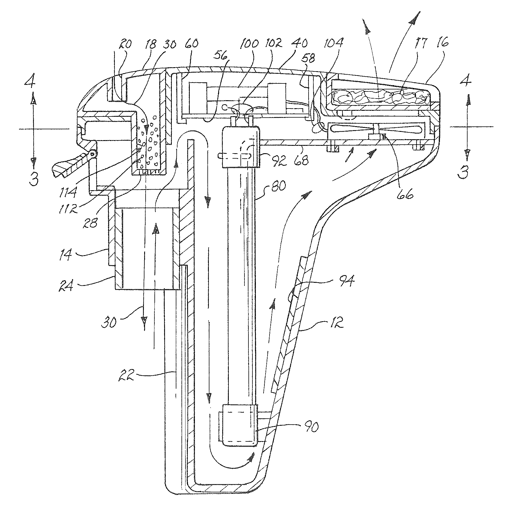
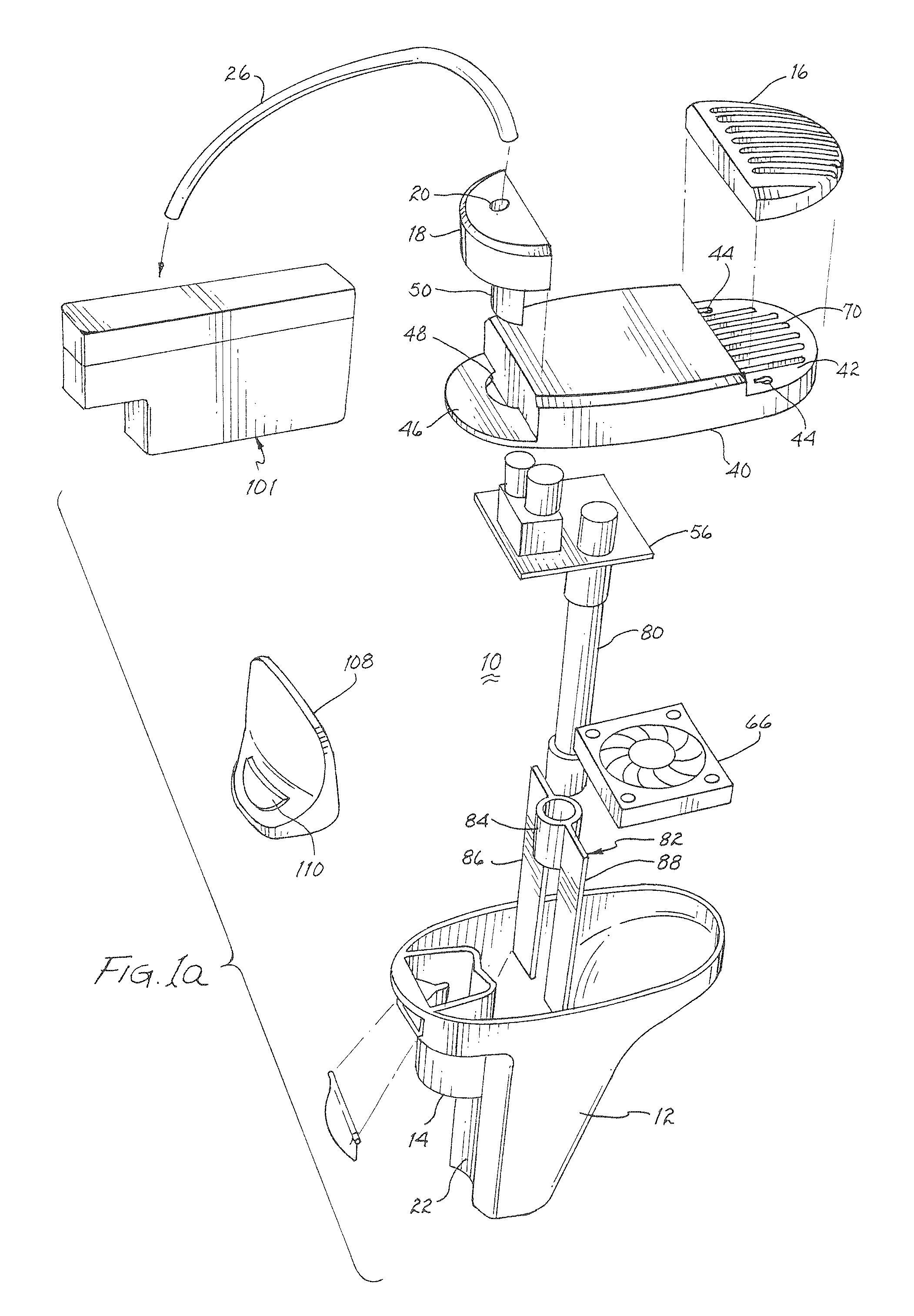
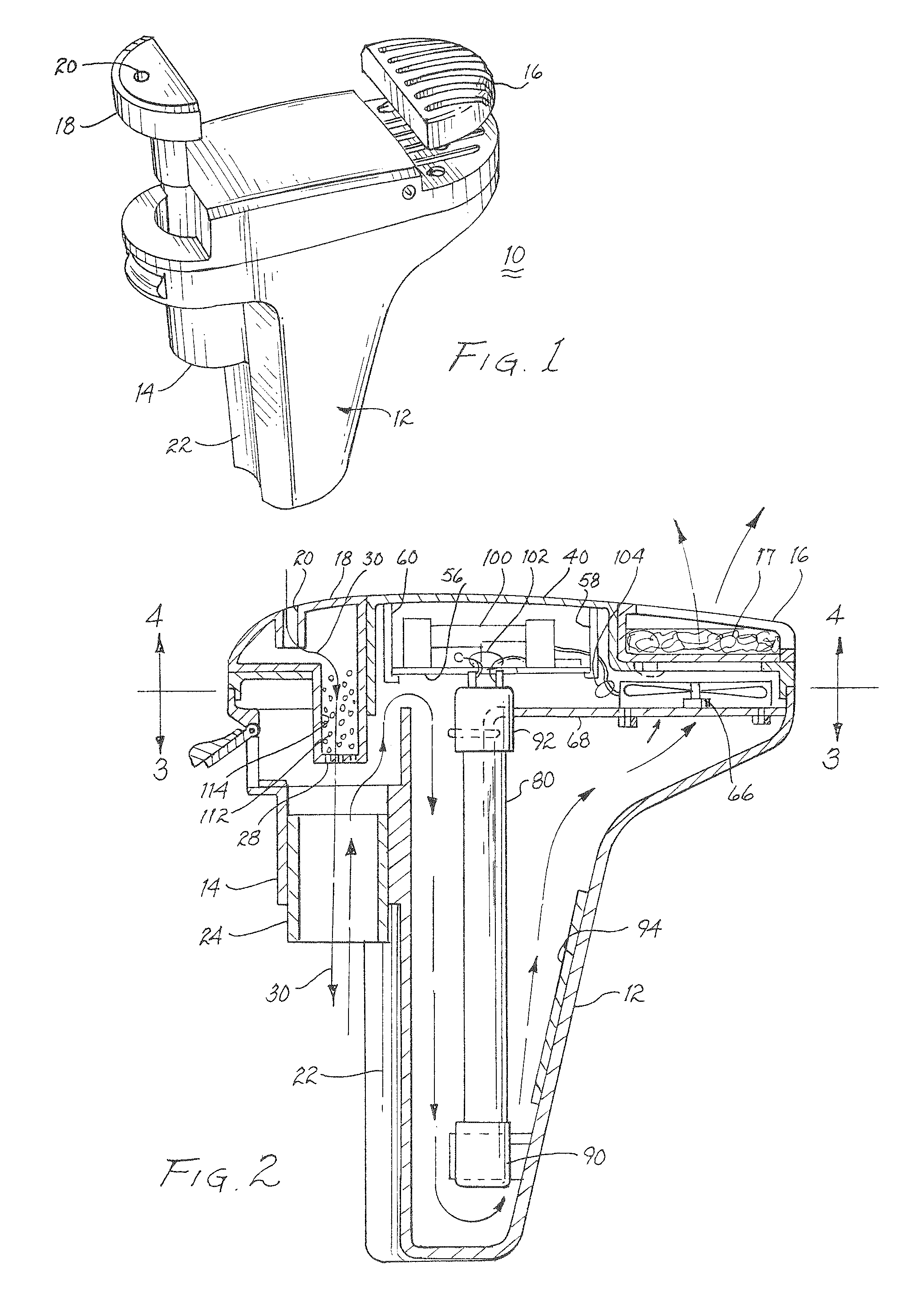
[0035]FIG. 1 illustrates a self contained odor eliminator hereinafter referred to as unit 10. The unit includes a housing 12 having a downwardly opening cylinder 14 for receiving a conventional stand pipe mounted within a toilet water tank. A replaceable filter 16 may include a carbon mesh 17 for filtering the air exhausting from unit 10. An insert 18 includes a receiver 20 for engagement by a conventional fill tubing found within a toilet tank to provide a flow of water through the stand pipe during the flushing and fill cycles. While receiver 20 is illustrated as a cylindrical cavity, it may be a nipple for gripping engagement by the fill tubing. Support for unit 10 within the toilet tank is provided by the stand pipe in engagement with cylinder 14. It may be noted that a concave depression 22 may be incorporated to receive a length of the stand pipe and provide further stability to unit 10 when mounted on the stand pipe.

[0036]Referring jointly to FIGS. 1a, 2, 3 and 4, further det...


PUM


Abstract

A self contained battery energized apparatus is mounted within the water tank of a conventional flush toilet to eliminate malodorous gases. Air from the toilet bowl is drawn through the stand pipe in the toilet tank into a housing to expose the air to UV radiation to produce ozone molecules that have an oxidizing effect on organic matter and the UV radiation serves as a germicide and a virucide. The ozonated and oxidized gases are exhausted through a carbon filter.

Description

CROSS REFERENCE TO RELATED APPLICATIONS[0001]The present application is related to and claims priority of a provisional application entitled “TOILET TANK MOUNTED ODOR ELIMINATOR”, filed Mar. 15, 2006, and assigned Ser. No. 60 / 782,467, disclosing an invention by the present inventors.BACKGROUND OF THE INVENTION[0002]1. Field of the Invention[0003]The present invention relates to apparatus for removing odors from toilet bowls and, more particularly, to apparatus for subjecting gases attendant a toilet bowl to ultraviolet radiation and ozone.[0004]2. Description of Related Prior Art[0005]Conventional flushing toilet bowls used throughout the world release odorous gases into the room upon use. A common solution to this problem is actuation of an exhaust fan to exhaust air and gases from the room through a ceiling mounted exhaust fan. Such exhaust fans may also be located in the walls of the room. These exhaust fans cause odorous gases to flow around and about an occupant and his / her clo...

Claims


Application Information

Patent Timeline
Patent Type & Authority Patents(United States)
IPC IPC(8): E03D9/04E03F5/08E03D9/00E03D9/02
CPCE03D9/052
Inventor DENKEWICZ, JR., RAYMOND P.ENGELHARD, ROLF
Owner ZUCO WATER LLC
Learn More