Vehicle air conditioning system

a technology for air conditioning systems and vehicles, applied in indirect heat exchangers, lighting and heating apparatuses, transportation and packaging, etc., can solve the problems of reducing cycle reliability, reducing operating range, and raising the temperature of coolant discharged from the compressor, so as to reduce the number of assembly steps, simplify the piping structure, and enhance the cycle reliability

Inactive Publication Date: 2012-04-24
CALSONIC KANSEI CORP
View PDF16 Cites 3 Cited by
  • Summary
  • Abstract
  • Description
  • Claims
  • Application Information

AI Technical Summary

Benefits of technology

[0006]With this taken into consideration, the present invention has been made for the purpose of solving the foregoing problem. An object of the present invention is to provide a vehicle air conditioning system capable of: operating at the optimum condition regardless of the number of evaporators; enhancing the cycle reliability to a large extent with no restriction being imposed on the conditions for the system operation; and simplifying the piping structure and thus reducing the number of assembly steps.

Problems solved by technology

As a result, in this vehicle air conditioning system, in a case where only the front-seat air conditioning unit is put in operation for example, only the evaporator located in the front seat side is used, too much superheat is supplied to the coolant, and thus the temperature of the coolant discharged from the compressor is raised.
This results in decrease in the cycle reliability, and in restricting the operating range.

Method used


Image

  • Vehicle air conditioning system
  • Vehicle air conditioning system
  • Vehicle air conditioning system

Examples


Embodiment Construction

[0011]Referring to the drawings, detailed descriptions will be provided below for a concrete embodiment to which the present invention is applied.

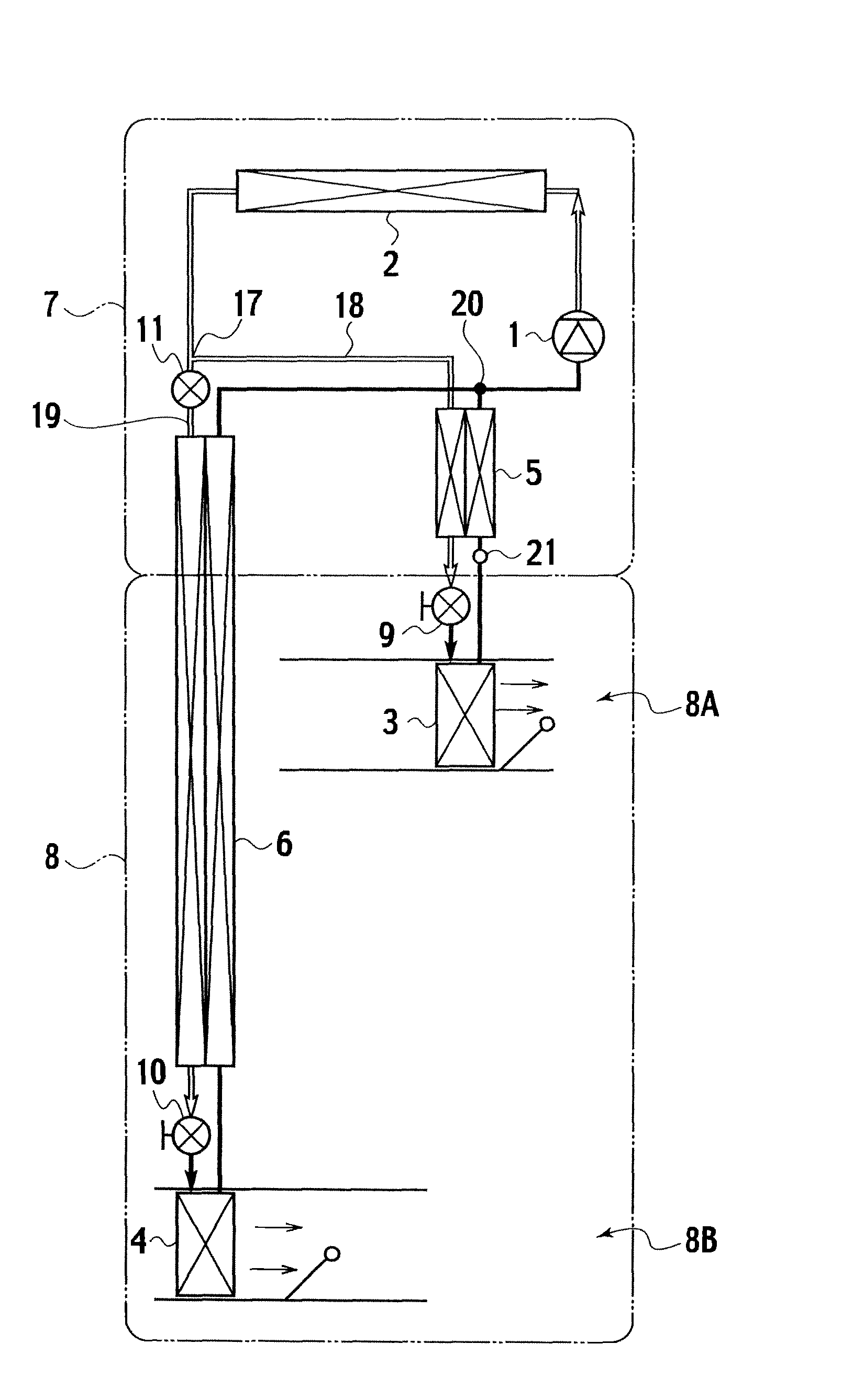
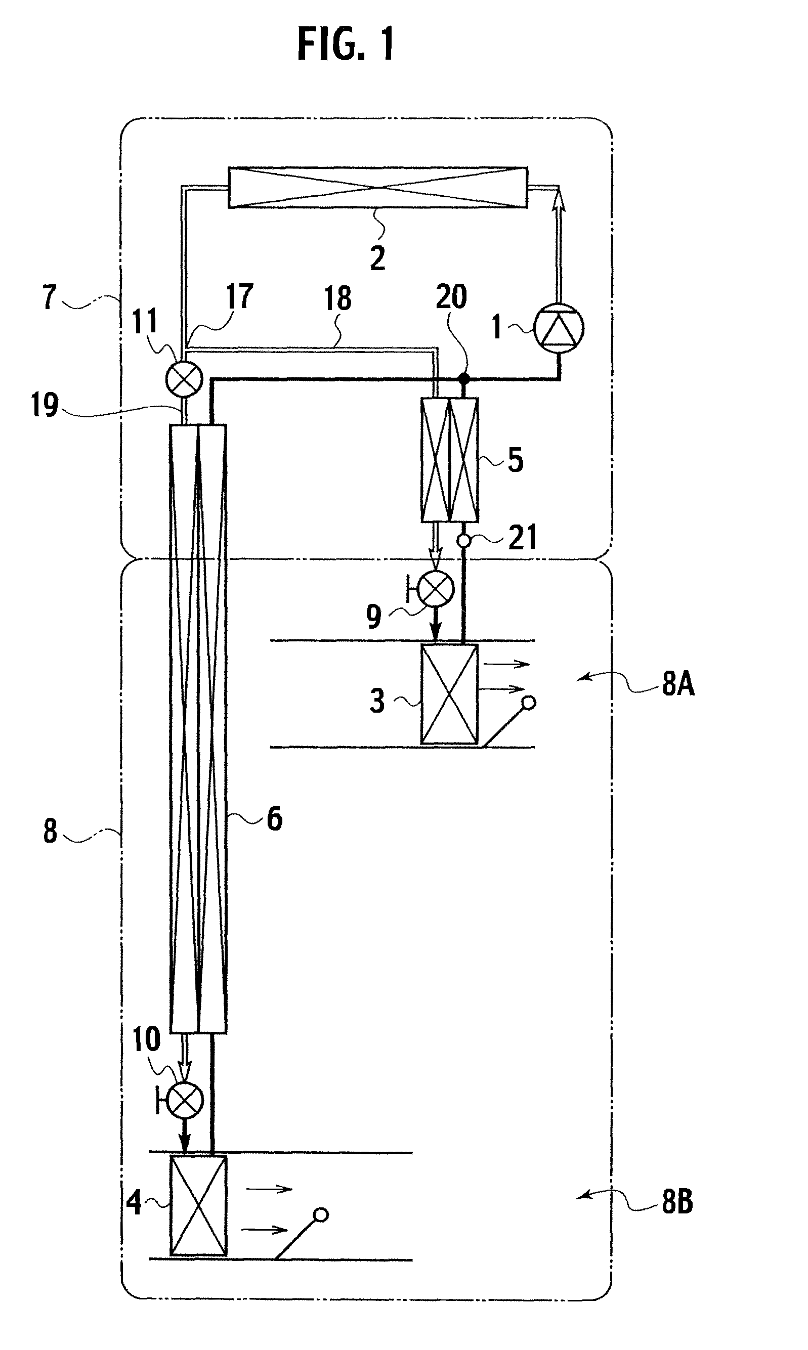
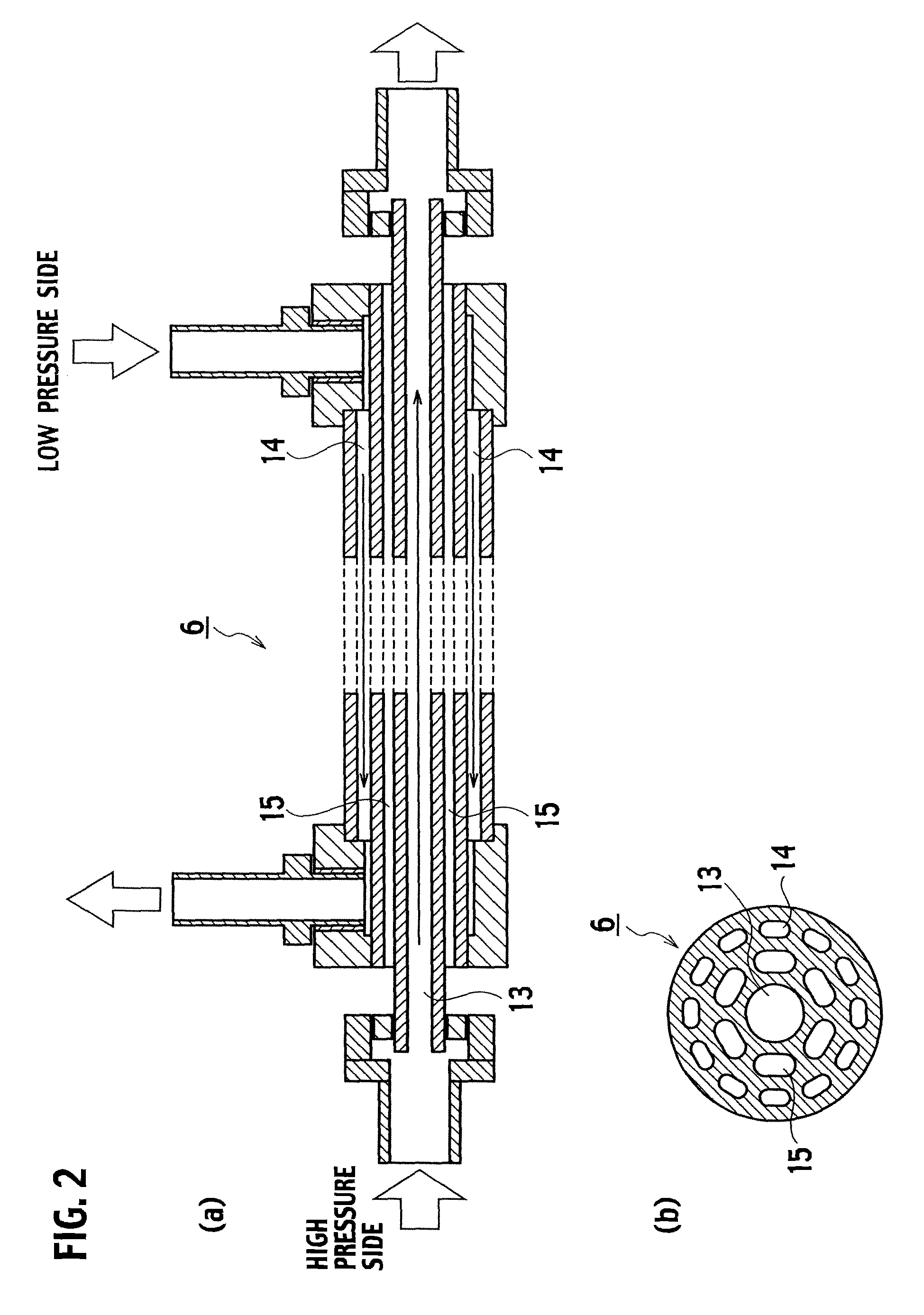
[0012]FIG. 1 is a system diagram of a vehicle air conditioning system according to the present embodiment. FIG. 2(a) is a vertical sectional view of an internal heat exchanger connected to a second evaporator in the vehicle air conditioning system according to the present embodiment. FIG. 2(b) is a horizontal sectional view of the internal heat exchanger connected to the second evaporator in the vehicle air conditioning system according to the present embodiment. FIG. 3 is a cross-sectional view showing another example of the internal heat exchanger connected to the second evaporator in the vehicle air conditioning system according to the present embodiment.

[0013]The vehicle air conditioning system according to the present embodiment uses carbon dioxide gas as its coolant. The vehicle air conditioning system includes: a compressor 1 which ...


PUM


Abstract

Disclosed is a vehicle air conditioning system including not less than two evaporators 3, 4, in which internal heat exchangers 5, 6 are provided to the respective evaporator 3, 4, a first evaporator 3 is placed in a front part of a compartment 8A whereas a second evaporator 4 is placed in a rear part of the compartment 8B; and the second evaporator 4 is connected to the internal heat exchanger 6 extended from the engine room 7 to the compartment 8. The internal heat exchanger 6 has a triple tube structure in which a heat insulator 15 is provided between a high-pressure medium passage 13 and a low-pressure medium passage 14.

Description

TECHNICAL FIELD[0001]The present invention relates to an air conditioning system for a vehicle, particularly to a vehicle air conditioning system of a dual air conditioner type.BACKGROUND ART[0002]Japanese Patent Application Laid-open Publication No. 2004-106799 discloses a vehicle air conditioning system of a dual air conditioner type including: a front-seat air conditioning unit for conditioning air for the front seat; and a rear-seat air conditioning unit for conditioning air for the rear seat.[0003]This type of vehicle air conditioning system has a configuration in which evaporators are provided respectively to the front-seat air conditioning unit and the rear-seat air conditioning unit, and in which one internal heat exchanger is employed as a common heat exchanger between the front-seat and rear-seat air conditioning units.DISCLOSURE OF THE INVENTION[0004]In a case where the single internal heat exchanger is used commonly by the front-seat and rear-seat air conditioning units ...

Claims


Application Information

Patent Timeline
Patent Type & Authority Patents(United States)
IPC IPC(8): F25B41/00B60H1/32B60H1/00
CPCB60H1/323F25B5/02F25B40/00F28D7/0008B60H2001/00957F25B9/008F25B2309/061F25B2600/2511
Inventor TAKAHASHI, TORAHIDEFUKUTOMI, YOSHITOMOKOBORI, YUKITOSHI
Owner CALSONIC KANSEI CORP
Why Eureka
Try Eureka