Circuit compensation in strain gage based transducers

a transducer and circuit compensation technology, applied in the field of strain gage, can solve the problems of inability to provide any improvement in creep tc performance, its applicability only to mixed-resin backing systems, and more complex and costly strain gage design and production

Active Publication Date: 2012-04-24
VISHAY MEASUREMENTS GROUP
View PDF22 Cites 4 Cited by
  • Summary
  • Abstract
  • Description
  • Claims
  • Application Information

AI Technical Summary

Problems solved by technology

While achieving an excellent creep result at one temperature is possible using the method, it does not, however, necessarily provide any improvement in creep TC performance over the more commonly practiced use of identical strain gages.
One obvious limitation with this technique is its applicability only to mixed-resin backing systems, which is not the dominant type used within the industry.
Achieving high resolution creep compensation over the entire −10 to +40° C. temperature range is a challenging aspect of these prior methods.
Disadvantages of this method are 1) more complex and costly strain gage design and production; and, 2) careful and selective ‘trimming’ of the creep characteristic in situ.
Thus, the prior methods have embraced a common result, where creep compensation is achieved via physical cancelling (viz., the positive counterforce creep is countered by the combined negative tension / compression strain gage creep), but it has not addressed the problem through electrical cancelling as disclosed herein.

Method used


Image

  • Circuit compensation in strain gage based transducers
  • Circuit compensation in strain gage based transducers
  • Circuit compensation in strain gage based transducers

Examples


Embodiment Construction

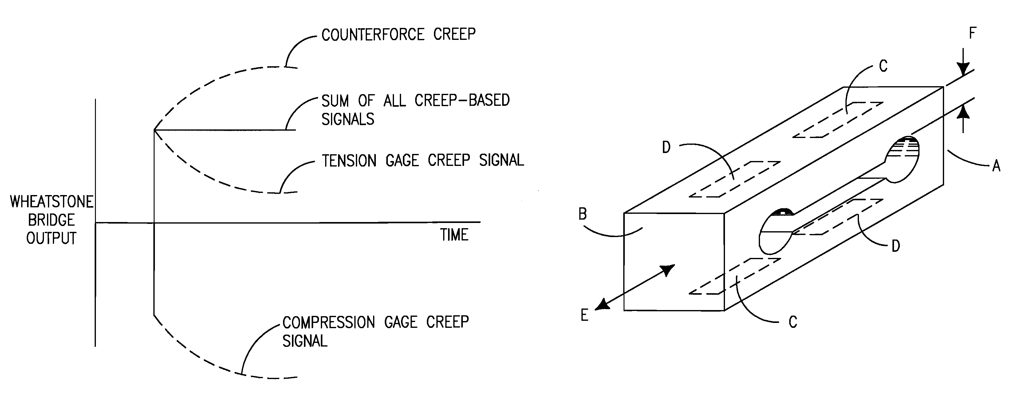
[0037]FIG. 8 illustrates a binocular transducer counterforce design. The counterforce is fixed at one end, A, and loaded with a deadweight (physical load) on the opposite end, B. The locations indicated by C are areas of tension strain (positive) and the locations indicated by D are areas of compressive strain (negative). Strain gages are normally attached with their major measurement axis (J in FIG. 4) aligned with the major measurement axis E of the counterforce. If it is desired to compensate for other responses of the transducer from weight or environment, the strain gage may be offset slightly (rotated or displaced) from perfect alignment in the direction of E, the disclosed structure remains valid and works well.

[0038]The strain gages are fixed to the counterforce, such as by an adhesive, direct lamination or some other process, and are wired into a Wheatstone bridge circuit as illustrated in FIG. 9b. The only criterion being that the four strain gages are suitably electricall...


PUM

PropertyMeasurementUnit
temperatureaaaaaaaaaa
creepaaaaaaaaaa

Abstract

A methodology for selecting and properly placing foil strain gages on a transducer in a Wheatstone bridge, which provides a more consistent creep response, especially when the transducer temperature is changed. A transducer includes a counterforce subjected to a predetermined physical load that provides tension and compression strains (positive and negative, respectively). The transducer also includes a plurality of strain gage grids that are operatively attached to the counterforce in the tension and compression strain areas of the counterforce and generate electrical signals. The plurality of strain gages are electrically connected in a Wheatstone bridge circuit where their electrical signals due to creep are cancelled.

Description

CROSS REFERENCE TO RELATED APPLICATION(S)[0001]This application claims the benefit of U.S. Provisional Application No. 61 / 229,123 filed Jul. 28, 2009, which is incorporated by reference as if fully set forth.FIELD OF INVENTION[0002]The present disclosure relates to strain gages and more particularly, to strain gages including creep compensation.BACKGROUND[0003]Strain gage based transducers are used in a variety of applications to convert mechanical inputs (for example, weight, force, mass, torque, pressure, deflection / displacement) into an electrical output. The basis for all such devices is the same. Specifically, a mechanical reaction device (commonly called a spring or counterforce) is designed to respond to the specific input, transducing the input into a measurable surface strain, which changes proportionally with the applied input. Strain gages attached to the transducer counterforce sense and respond to this surface strain with a change in electrical resistance. The counterfo...

Claims


Application Information

Patent Timeline
Patent Type & Authority Patents(United States)
IPC IPC(8): G01L1/00G01L5/24
CPCG01B7/18G01B21/045G01L1/2243G01L1/2262G01L1/2281Y10T29/49007
Inventor ZANDMAN, FELIXWATSON, ROBERT B.KIEFFER, THOMAS P.
Owner VISHAY MEASUREMENTS GROUP
Why Eureka
Try Eureka