Dome shaped implant and inserter

a technology of implant and inserter, which is applied in the direction of prosthesis, shoulder joints, ligaments, etc., can solve the problems of difficult handling of such fixation devices, minimal visibility and access to the joint structure, and the insertion of these implants is difficult. to achieve the effect of facilitating the handling and subsequent insertion

Active Publication Date: 2012-04-24
ARTHREX
View PDF10 Cites 72 Cited by
  • Summary
  • Abstract
  • Description
  • Claims
  • Application Information

AI Technical Summary

Problems solved by technology

Insertion of these implants, is typically problematic as it is difficult to handle such fixation devices within the joint capsule (during arthroscopic surgery, for example) where visibility and access to the structures of the joint is minimal.
It is also difficult to precisely position such fixation devices at the arthroscopic site.

Method used


Image

  • Dome shaped implant and inserter
  • Dome shaped implant and inserter
  • Dome shaped implant and inserter

Examples


Embodiment Construction

[0015]In the following detailed description, reference is made to various specific embodiments in which the invention may be practiced. These embodiments are described with sufficient detail to enable those skilled in the art to practice the invention, and it is to be understood that other embodiments may be employed, and that structural and logical changes may be made without departing from the spirit or scope of the present invention.

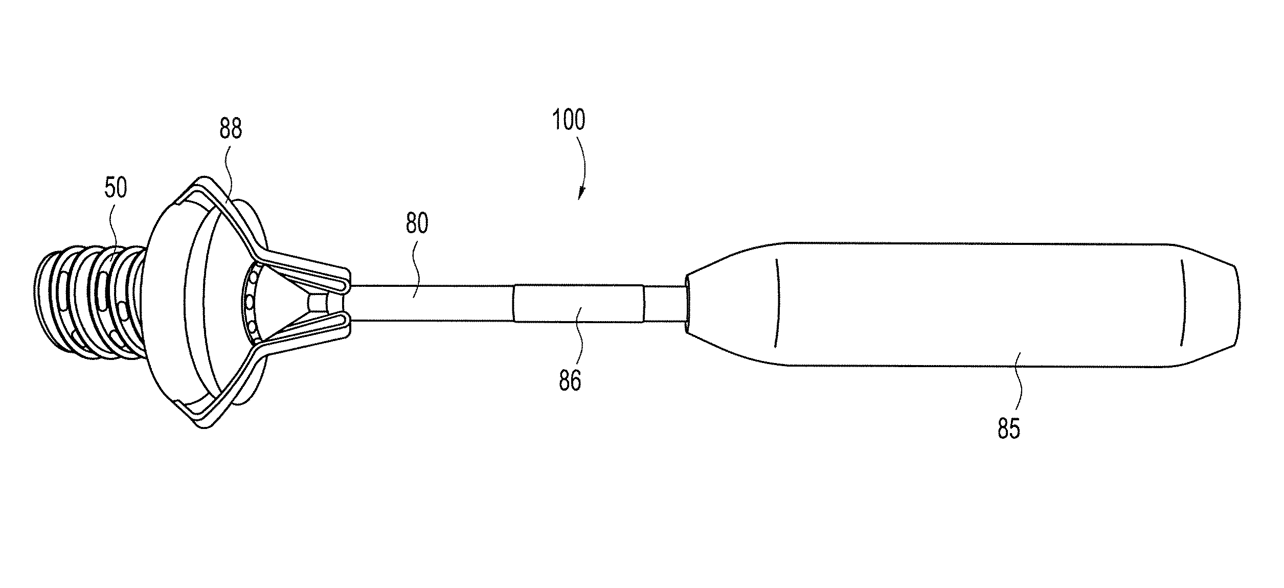
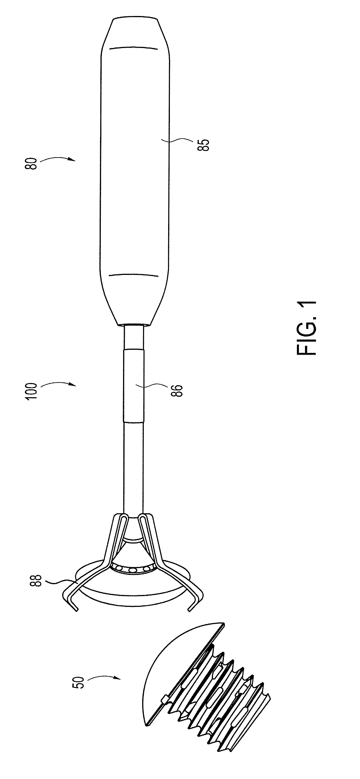
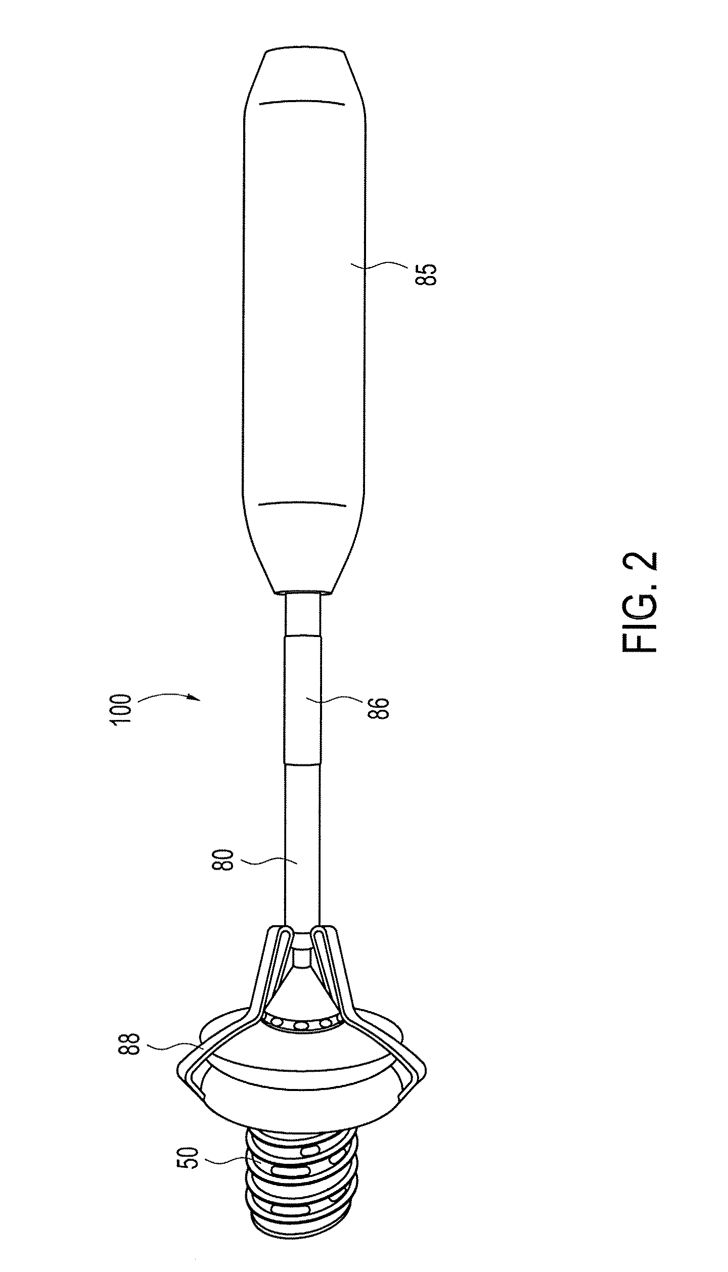
[0016]The present invention provides a dome shaped implant and an inserter that is configured to allow improved handling of the implant within a joint capsule, for example the knee capsule or the shoulder joint, during surgical reconstruction.

[0017]The implant of the present invention is designed to be securely engaged by a corresponding inserter or driver. The implant is preferably provided with a dome or eclipse-like head having a plurality of indents on the periphery of the head. The plurality of indents are configured to be engaged by arms (tabs) ...


PUM


Abstract

An implant for resurfacing a joint and a driver for the implant. The inserter attaches to the head of the implant. The inserter is designed to facilitate the handling and insertion of an implant at a surgical site. The inserter is provided with a plurality of arms that securely engage a plurality of indents on the edge or periphery of the implant.

Description

CROSS REFERENCE TO RELATED APPLICATIONS[0001]This application claims the benefit of U.S. Provisional Application Ser. No. 60 / 910,073 filed on Apr. 4, 2007, the entire disclosure of which is incorporated by reference in its entirety herein.FIELD OF THE INVENTION[0002]The present invention relates to a dome shaped implant for joint resurfacing and an inserter for the implant.BACKGROUND OF THE INVENTION[0003]When a bearing surface of a joint becomes damaged, one solution is to replace the damaged surface with an implant having a hemispherical surface that matches the contour of the damaged cartilage of the joint. Insertion of these implants, is typically problematic as it is difficult to handle such fixation devices within the joint capsule (during arthroscopic surgery, for example) where visibility and access to the structures of the joint is minimal. It is also difficult to precisely position such fixation devices at the arthroscopic site.[0004]Accordingly, a need exists for a surgic...

Claims


Application Information

Patent Timeline
Patent Type & Authority Patents(United States)
IPC IPC(8): A61F2/46
CPCA61F2/3877A61F2/40A61F2/461A61F2/4612A61F2/42A61F2/4606A61F2002/4628
Inventor DREYFUSS, PETER J.
Owner ARTHREX
Why Eureka
Try Eureka