Display device

a display device and display technology, applied in the field of display devices, can solve the problems of deteriorating reliability and operating life of not only the led but also the peripheral components, and the inability to accurately detect the input position, etc., and achieve the effect of long life and high brightness

Inactive Publication Date: 2012-04-24
GK BRIDGE 1
View PDF7 Cites 3 Cited by
  • Summary
  • Abstract
  • Description
  • Claims
  • Application Information

AI Technical Summary

Benefits of technology

[0011]The present invention addresses the problems above. It is therefore an object of the invention to provide a long-life and highly bright display device. The display device attains a reliable data-input to the digitizer, and at the same time, provides sufficient radiation of heat generated from the LEDs.

Problems solved by technology

The increase in temperature can deteriorate reliability and operating life of not only the LED but also peripheral components.
In the structure above, however, a problem arises.
When a metal including a heat-dissipation plate is disposed within the valid display area, the metal inconveniently affects the magnetic field between the digitizer and the pen, so that an accurate detection of an input position cannot be expected.

Method used


Image

  • Display device
  • Display device
  • Display device

Examples


first embodiment

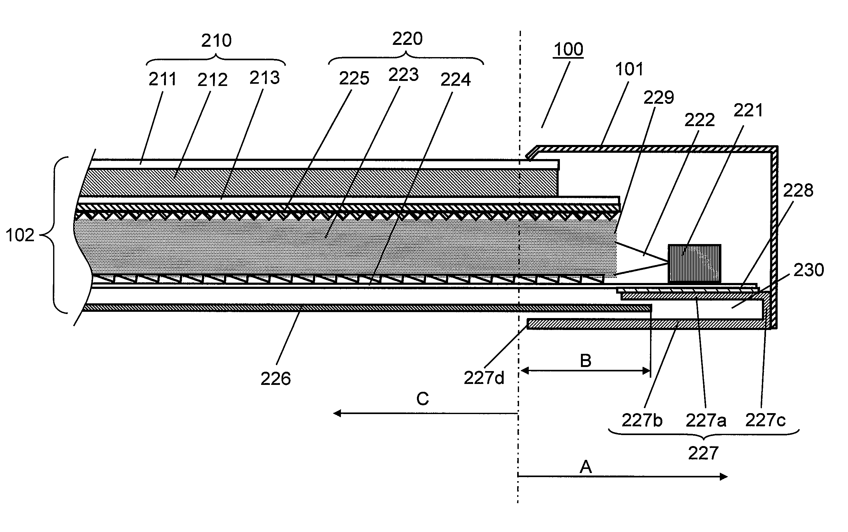
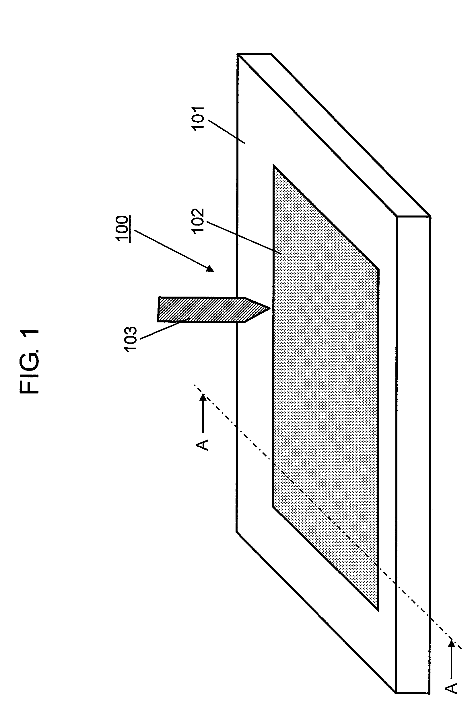
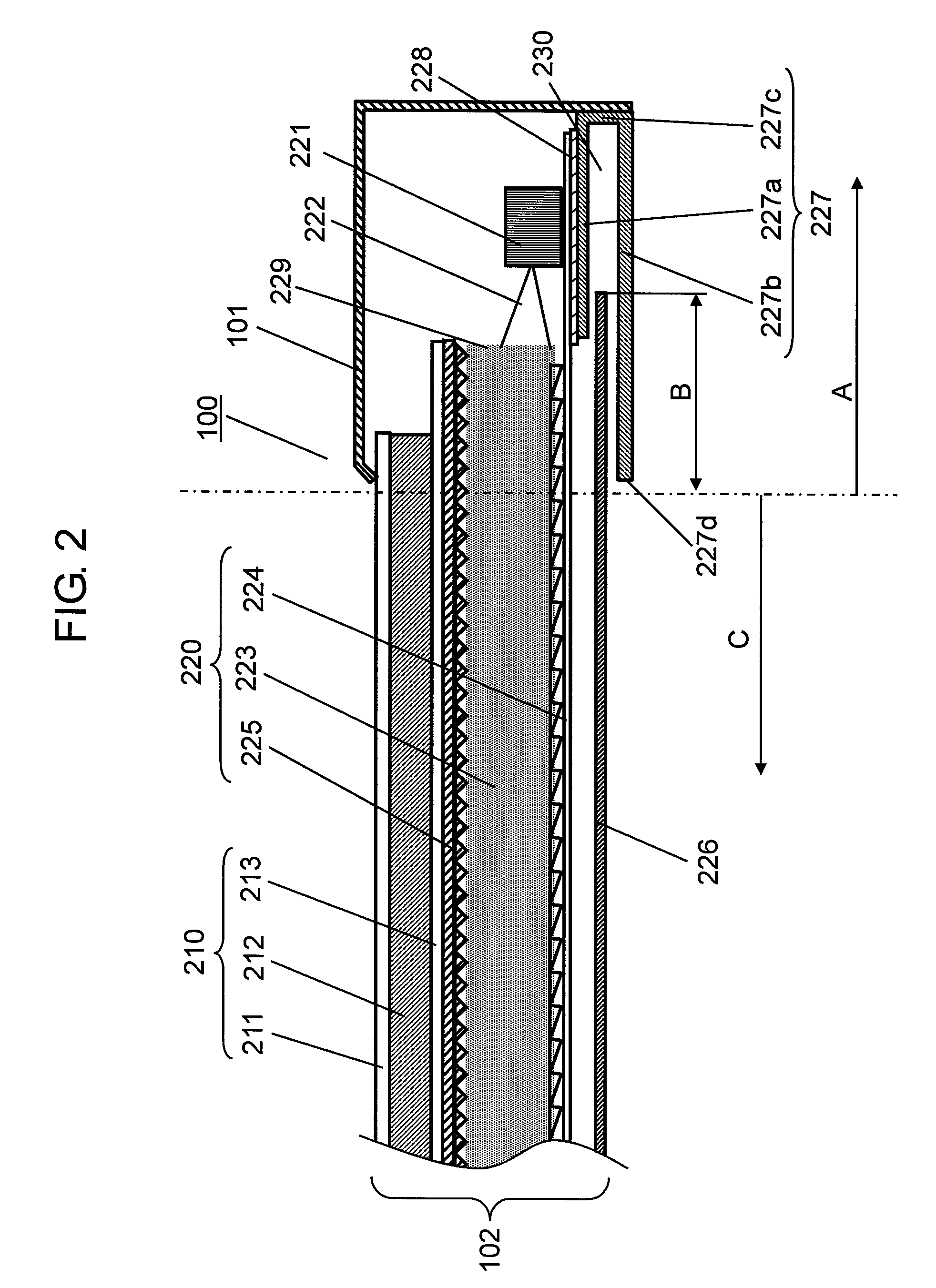
[0018]FIG. 1 is a perspective view of the display device in accordance with the first exemplary embodiment of the present invention. FIG. 2 is a partly shown sectional view, taken along line A-A, of the display device of FIG. 1. As is shown in FIG. 1, the periphery of display device 100 is covered with resin-made housing 101. LCD panel 102 is disposed inside display device 100 and housing 101. Electromagnetic digitizer 226 is disposed on the back surface of LCD panel 102. When a user operates electromagnetic stylus 103 close to the screen of LCD panel, digitizer 226 detects the position data required for data processing operation. Although LCD panel 102 is sandwiched between a front glass substrate and a back glass substrate, the two substrates are omitted in the drawings.

[0019]LCD panel 102, as is shown in FIG. 2, is formed of LCD section 210 and backlight source section 220. LCD section 210 further contains outgoing-light polarizing plate 211, LCD body 212, and incoming-light pola...

second embodiment

[0036]FIG. 3 is a partly shown sectional view of the display device in accordance with the second exemplary embodiment of the present invention. The display device of the embodiment has a structure basically the same as that of display device 100 described in the first embodiment—with the exceptions of the structures of end section A and the housing.

[0037]As is shown in FIG. 3, LCD panel 302 of display device 300 is formed of LCD section 310 and backlight source section 320. LCD section 310 further contains outgoing-light polarizing plate 311, LCD body 312, and incoming-light polarizing plate 313. Backlight source section 320 further contains LED 321 as a light source, light-guide plate 323 for leading white light 322 emitted from LED 321, reflection sheet 324, and prism sheet 325. LED 321 is disposed at an end of one shorter-side of display device 300. Reflection sheet 324 is disposed on the back surface of light-guide plate 323. On the other hand, prism sheet 325 is disposed on th...

third embodiment

[0049]FIG. 4 is a partly shown sectional view of display device 400 in accordance with the third exemplary embodiment of the present invention. Display device 400 of the embodiment has a structure basically the same as that of display device 300 described in the second embodiment—with the exception of the structure of end section A.

[0050]As is shown in FIG. 4, LCD panel 402 of display device 400 is formed of LCD section 410 and backlight source section 420. LCD section 410 further contains outgoing-light polarizing plate 411, LCD body 412, and incoming-light polarizing plate 413. Backlight source section 420 further contains LED 421 as a light source, light-guide plate 423 for leading white light 422 emitted from LED 421, reflection sheet 424, and prism sheet 425. LED 421 is disposed at an end of one shorter-side of display device 400. Reflection sheet 424 is disposed on the back surface of light-guide plate 423. On the other hand, prism sheet 425 is disposed on the front surface of...


PUM


Abstract

The display device has an LCD panel, a light source, and a digitizer disposed on the back surface of the LCD panel. The display device further contains a U-shaped first heat-dissipation plate made of a non-magnetic material. The first heat-dissipation plate is disposed on at least one end of the periphery of the LCD panel in a way that the opening of the U-shape faces toward the LCD panel. The light source is mounted on the first heat-dissipation plate, and an end section of the digitizer is covered with the opening of the plate.

Description

FIELD OF THE INVENTION[0001]The present invention relates to a display device having a backlight source, and specifically relates to a display device having an electromagnetic digitizer.BACKGROUND ART[0002]In recent years, a display device with a liquid crystal display (LCD) panel has become the mainstream for display devices. In such an LCD device, a thin film transistor (TFT) is formed on a glass substrate, and a backlight source is disposed on the rear side of an LCD panel in which liquid crystal elements are arranged. The backlight source emits light and the light goes through the panel, so that an image is shown on the display of the device. To obtain clear and bright images with high quality, the backlight source has to provide light with high brightness and uniformity on the display.[0003]Conventionally, a cold-cathode tube has been used as a backlight source for a display device having an LCD panel. However, recent technical advances in light emitting diode (LED)s have drast...

Claims


Application Information

Patent Timeline
Patent Type & Authority Patents(United States)
IPC IPC(8): G06F3/033
CPCG02B6/0085G02F1/13338G06F3/0412G06F3/046G02B6/0073G02F1/133615G02F2001/133628G02F1/133628
Inventor HATAKEYAMA, ATSUSHI
Owner GK BRIDGE 1
Why Eureka
Try Eureka