Radiation detector for density or level measurements

a technology of density or level measurement and radiation detector, which is applied in the direction of instruments, specific gravity measurement, machines/engines, etc., can solve the problems of difficult installation at the port, and achieve the effect of reasonable speedy level measurement and reduced temperature of associated apparatus

Active Publication Date: 2016-06-07
JOHNSON MATTHEY PLC
View PDF19 Cites 0 Cited by
  • Summary
  • Abstract
  • Description
  • Claims
  • Application Information

AI Technical Summary

Benefits of technology

[0020]The electronic apparatus associated with a nucleonic instrument according to the invention, comprising the control system, signal and data processing device, power source and optionally equipment such as data loggers and transmitting equipment, is normally housed within an enclosure in order to protect it from the environment. The enclosure is designed to withstand the conditions in which the instrument may be deployed, including those of super-ambient temperature and pressure. The temperature of the electronic apparatus within the enclosure is desirably maintained within a temperature range in which it can operate according to its designed function. Preferably the electronic apparatus is maintained at a temperature less than 120° C., more preferably less than 100° C. A temperature sensor may be provided to monitor the temperature at one or more locations within the enclosure. The enclosure may be supported mounted adjacent to the detector probe and source array or may alternatively be mounted in a position which is spaced apart from the detector probe and source array. In the latter case, communication means, which may be wireless or wired, are provided to carry electrical signals between the detector probe and the electronic apparatus. The detector probe tends to conduct heat to or away from any associated electrical control system or data processing apparatus. When the detector probe is subjected to very high temperatures a corresponding increase in the temperature of associated apparatus may be reduced by means of thermal insulation placed between the detector probe and the associated apparatus. The enclosure may contain insulation material in order to thermally insulate the electronic apparatus from heat conducted by the detector probe and / or the source array, and / or to insulate the electronic apparatus from hot or cold external temperatures. In a preferred embodiment, the instrument comprises thermal insulation between the detector probe on the one hand and the power source and electronic apparatus on the other hand. In this way the electronic control, signal / data processing components and power source may be protected from high temperatures which might adversely affect their operation.
[0021]The nucleonic instrument of the invention comprises a source of ionising radiation and a detector probe as hereinbefore described, said source and detector probe being arranged so that ionising radiation from the source passes along a straight line through a portion of the container to the detector probe. The source is mounted within a radiation shielding material which includes collimation means for producing a collimated beam of radiation which is directed towards the detectors. The source and / or detector probe may be mounted outside or inside a vessel containing the material to be measured. When the source is mounted outside the vessel and the radiation is to traverse at least one vessel wall, the source must be selected to produce radiation of sufficient energy to penetrate the walls of the vessel. The source should also be selected to be of sufficient activity to produce sufficient counts in the detector(s) in order that a reproducible signal may be generated by the detectors which is proportional to the radiation detected within about a second so that level measurement may be carried out reasonably quickly.

Problems solved by technology

In some circumstances it is desirable to reduce the cross-section of the profiler device even more in order to access installations in which the size of the port or the space around the port makes installation particularly difficult.

Method used


Image

  • Radiation detector for density or level measurements
  • Radiation detector for density or level measurements
  • Radiation detector for density or level measurements

Examples


Embodiment Construction

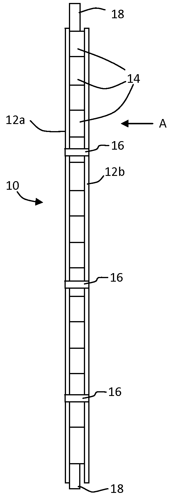
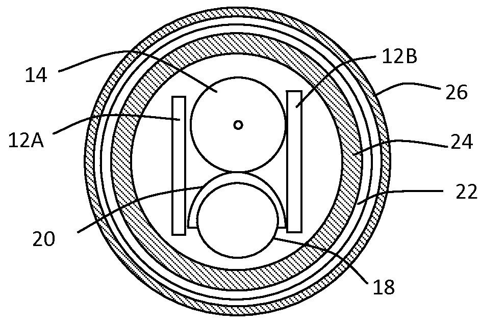
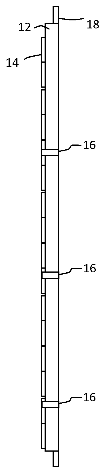
[0032]FIGS. 1 & 1A show a detector probe 10, comprising two printed circuit boards 12a and 12b. A plurality of detectors 14 are mounted on the circuit boards in a linear arrangement. A steel rod 18 provides stiffness to the probe assembly. Straps 16 hold the assembled components together securely. A section through the detector probe, housed within a dip tube, is shown in FIG. 2. The detector probe is installed within a protective plastic tubular enclosure 22 which is housed within a cylindrical dip pipe 26. Thermal insulation 24 is provided inside the tube 22.

[0033]FIG. 3 shows an elevation of a density profiler instrument 30 according to a preferred embodiment of the invention. The instrument comprises a steel housing, shown in section, comprising a flanged support structure 48 and a domed cover 32. The housing contains at least a high voltage generator 42, data loggers, counters, signal processing means and data processors 44, means for supplying power to the voltage generator 46...


PUM

PropertyMeasurementUnit
diameteraaaaaaaaaa
thicknessaaaaaaaaaa
voltageaaaaaaaaaa

Abstract

A nucleonic density profiler includes a detector probe, for detecting ionizing radiation, includes an array of sources of ionizing radiation, an array of radiation detectors and a circuit board including at least two circuit board portions. A power source and electronic apparatus includes a control unit and a signal and data processor for calculating a density profile of the material phases using signals generated by the detectors in response to radiation received from the radiation sources.

Description

BACKGROUND OF THE INVENTION[0001]1. Field of the Invention[0002]The present invention relates to an apparatus for measuring levels of materials, especially of fluids, and optionally for calculating a density profile of a mixed fluid system.[0003]2. Description of the Related Art[0004]A density profiler has been described in WO2000 / 022387. The device comprises a linear array of sources of ionising radiation which emit radiation towards detectors disposed in one or more linear arrays. When the source array and detector array(s) are positioned so that they traverse the interfaces between two or more fluids in a container, the interfaces of the fluids may be identified from the differences in radiation received by each detector in the array. The device has been successfully deployed for use in storage tanks and oil separators. A desirable feature of the profiler device is its compact diameter which enables it to be fitted into a vessel through a standard access port. In some circumstanc...

Claims


Application Information

Patent Timeline
Patent Type & Authority Patents(United States)
IPC IPC(8): G01N9/24G01F23/288G01T1/18
CPCG01N9/24G01F23/288G01F23/2885G01T1/18G01T1/17G01T7/00
Inventor DALES, KEVAN BRADLEYHOUGH, TIMOTHYHOWE, GEOFFREY STUART
Owner JOHNSON MATTHEY PLC
Why Eureka
Try Eureka