
Speaker system and speaker cluster system

a speaker system and speaker technology, applied in the field of speaker systems and speaker cluster systems, can solve the problems of inability to control directivity stably and the inability to easily install the combined system in the acoustic space, and achieve the effect of constant directivity and wide frequency rang

Active Publication Date: 2012-04-24
TOA CORP
View PDF16 Cites 4 Cited by
  • Summary
  • Abstract
  • Description
  • Claims
  • Application Information

AI Technical Summary

Benefits of technology

[0032]In accordance with the present invention, constant directivity can be obtained in a wider frequency range. In addition, a directivity angle can be set as desired in a predetermined angle range.

Problems solved by technology

For this reason, the combined system is not easily installed in the acoustic space.
However, since the horn of the tweeter is relatively small, the directivity cannot be controlled stably in a frequency bandwidth so wide as that of the constant directivity horn.Non-Patent Document 1: Saeki Tamon “New edition speaker & enclosure encyclopedic information) (Japan) published by Seibundo Shinko Sya Co. Ltd. May 28, 1999, p 36 to 37

Method used


Image

  • Speaker system and speaker cluster system
  • Speaker system and speaker cluster system
  • Speaker system and speaker cluster system

Examples


Embodiment Construction

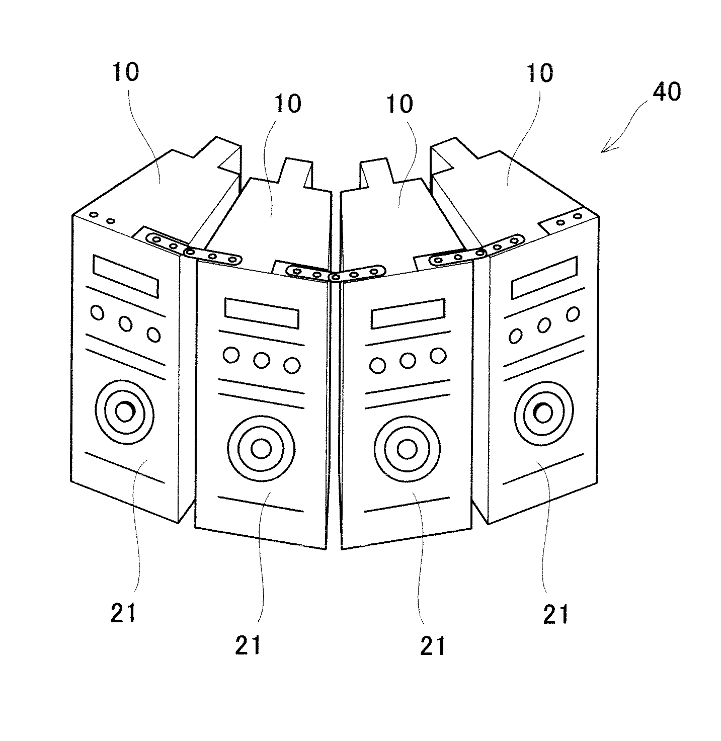
[0059]Hereinafter, a speaker system and speaker cluster system according to an embodiment of the present invention will be described with reference to the drawings.

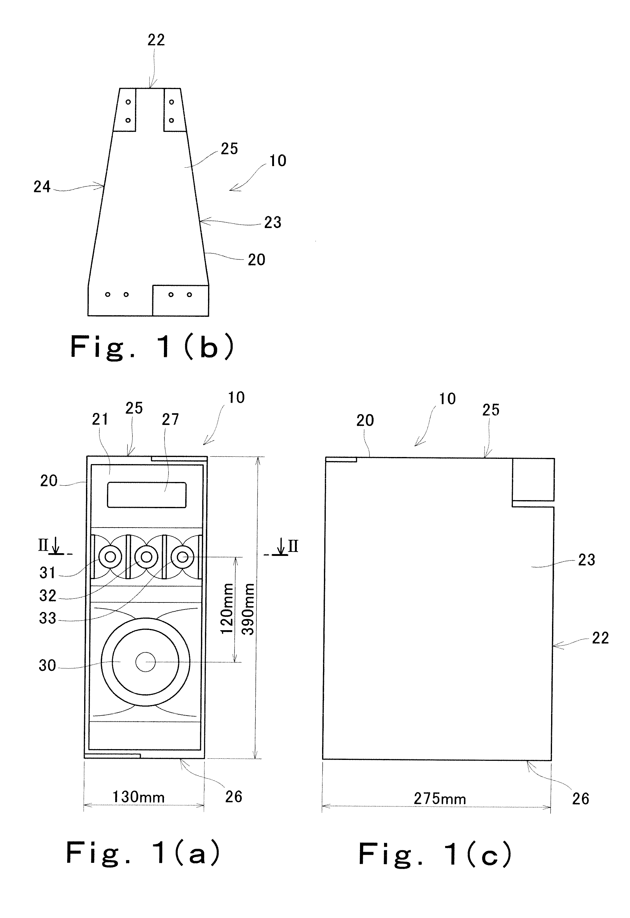
[0060]FIG. 1 is a view of a speaker system 10, wherein FIG. 1(a) is a front view thereof, FIG. 1(b) is a plan view thereof, and a FIG. 1(c) is a side view thereof. FIG. 1 shows schematic dimensions of the speaker system 10.

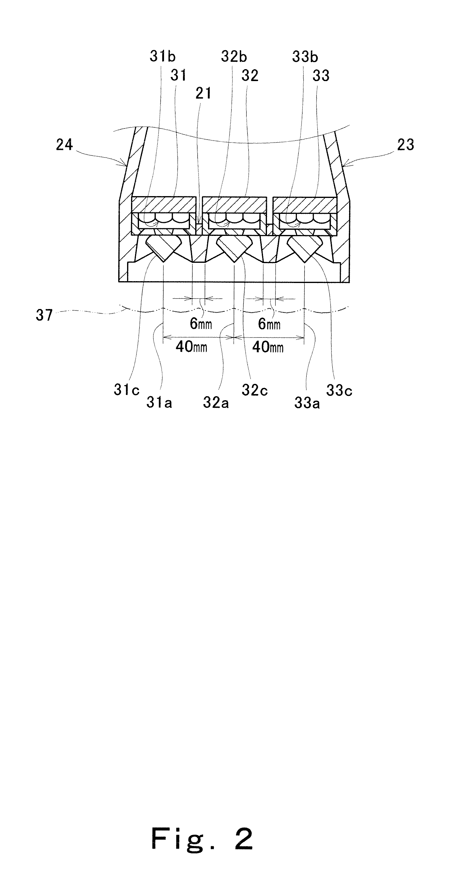
[0061]The speaker system 10 includes an enclosure 20, a woofer unit 30 which is a first speaker unit, and tweeter units 31, 32, and 33 which are second speaker units.

[0062]The enclosure 20 includes a front plate portion 21 which is a baffle plate, a rear plate portion 22, a left plate portion 23, a right plate portion 24, a top plate portion 25, and a bottom plate member 26. These plate portions form outer walls of the enclosure 20.

[0063]The rear plate portion 22 has a width smaller than that of the front plate portion 21. The left side plate portion 23 and the right side plate portion 24 are disposed b...


PUM


Abstract

A speaker system includes an enclosure, a first speaker unit for low frequency and a plurality of second speaker units for high frequency. The enclosure includes a front plate portion which is a baffle plate and a rear plate portion. A length of the rear plate portion in a first direction perpendicular to a forward and backward direction is shorter than a length of the front plate portion in the first direction. The first speaker unit and the second speaker units are mounted to the front plate portion. The plurality of second speaker units are arranged in the first direction. Vibration plates of the plurality of second speaker units are located in the vicinity of the front plate portions in the forward and backward direction.

Description

TECHNICAL FIELD[0001]The present invention relates to a speaker system and speaker cluster system that are capable of obtaining constant directivity in a wider frequency range and in a lower frequency.BACKGROUND ART[0002]For example, to provide a sound in a space (acoustic space) having a substantial capacity such as an airport lobby, a speaker system designed to obtain constant directivity in a frequency range is in some cases used. A typical example of such a speaker system is a speaker system using a constant directivity horn (see e.g., non-patent document 1).[0003]The speaker system using the constant directivity horn is frequently used in combination with a box speaker including a woofer unit attached to a cabinet. According to such a speaker system, in a frequency bandwidth provided by the constant directivity horn, directivity is controlled relatively stably. That is, constant directivity can be obtained in a relatively wide frequency range.[0004]The speaker system using the ...

Claims


Application Information

Patent Timeline
Patent Type & Authority Patents(United States)
IPC IPC(8): H04R25/00H04R1/02H04R1/26H04R27/00
CPCH04R1/26H04R27/00H04R2201/401
Inventor IWAYAMA, KEN
Owner TOA CORP
Learn More