
Microphone array

a microphone array and array technology, applied in the direction of transducer details, electrical transducers, signal processing, etc., can solve the problems of difficult to achieve good sound quality and speech intelligibility, and large amount of cabling, so as to achieve high directivity in the vertical direction

Active Publication Date: 2022-08-16
SENNHEISER ELECTRONICS GMBH & CO KG
View PDF12 Cites 0 Cited by
  • Summary
  • Abstract
  • Description
  • Claims
  • Application Information

AI Technical Summary

Benefits of technology

[0011]An object of the present invention is to provide a microphone arrangement with a particularly high directivity in vertical direction and a high yet in wide limits adjustable directivity in horizontal direction.
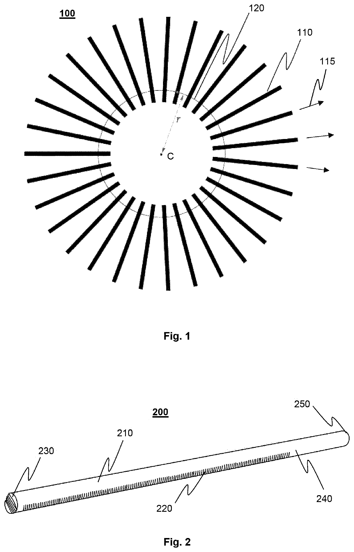
[0014]Due to the high directivity of the shotgun microphones, both the elevation angle and the azimuth angle of the detection area or coverage of the arrangement are very small, while the azimuth angle is adjustable in a very large range that may be up to 360°. The resulting azimuthal directivity of the microphone arrangement can be stronger than the directivity of a single shotgun microphone, even if none of the shotgun microphones points to the respective direction. In embodiments where the microphones are distributed over a full circle, there are always some shotgun microphones that point opposite to the actual target direction. This enables a constant directivity, regardless of the orientation of the microphone array.

Problems solved by technology

Due to the amount of ambient noise, it is difficult to achieve a good sound quality and speech intelligibility.
Similar problems may occur in other sports, such as, e.g., baseball, or in other situations where sound recordings are to be made from sound sources that are widely distributed over a plane area and that may be mobile and cannot be directly provided with a microphone, despite disturbing ambient noise.
A disadvantage of this known solution is that a large amount of cabling is required.
Additional microphones require additional cabling and make the system more expensive.
Nevertheless, these regions are captured with only poor sound quality and therefore suboptimal.
However, this is associated with a time delay.
With a possible remote control for aligning the microphones, both additional delay and motor noise would occur, which would inevitably be captured by the microphone and be hearable as disturbing noise.
This leads to a permanently changing tone or timbre of the sound signal.
Common algorithms are the Delay-and-Sum (DS) algorithm and the “Minimum Variance Distortionless Response” (MVDR) algorithm, which both have drawbacks, however.
Normally, microphone arrays are constructed from microphones without or with low directivity, since they are easy to handle and cheap.
This requires a very large number of microphones for obtaining a high directivity over a wide azimuth angle and a similar directivity with respect to elevation, leading to a high computation effort.

Method used


Image

  • Microphone array
  • Microphone array
  • Microphone array

Examples


second embodiment

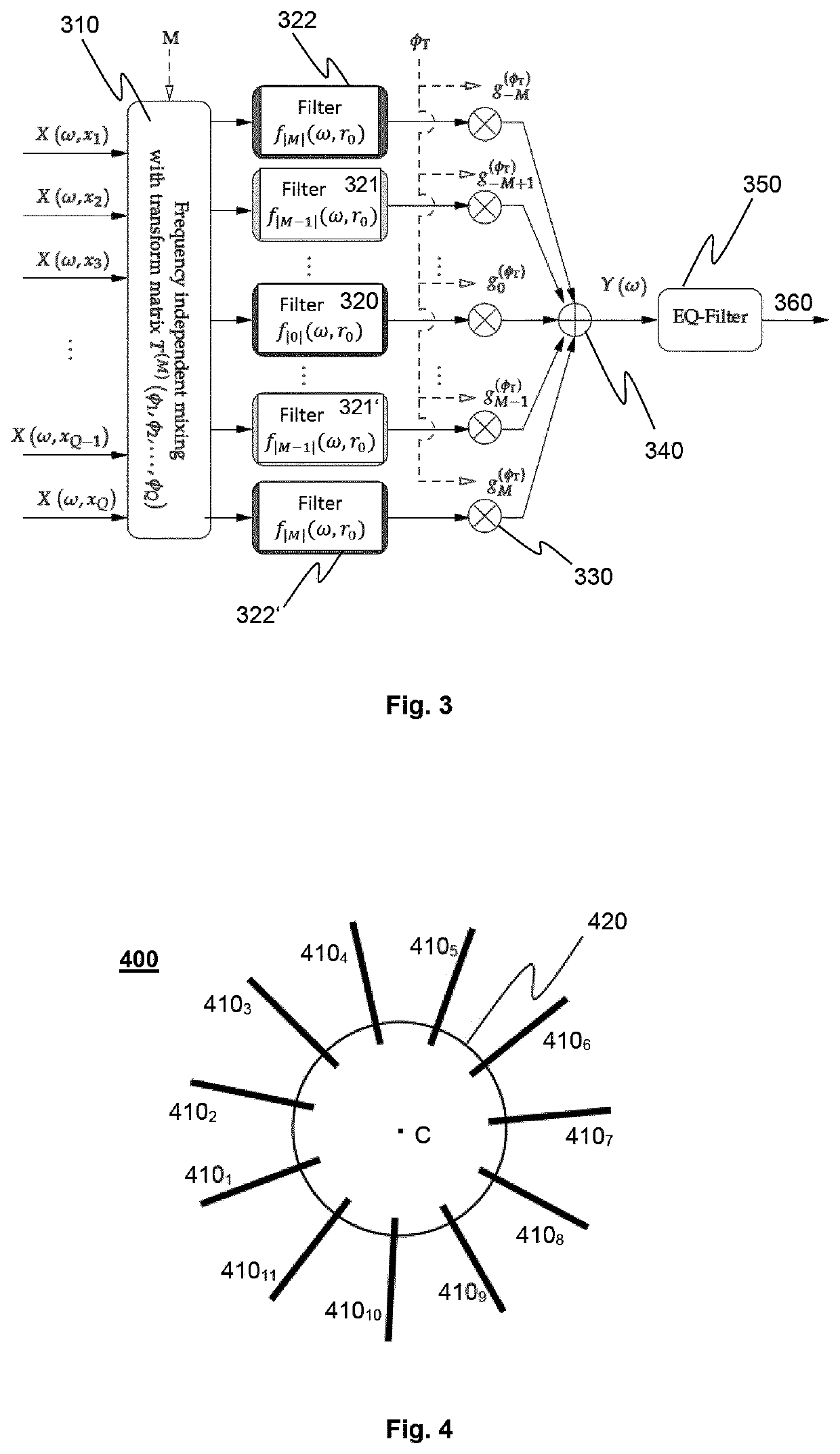
[0039]FIG. 4 shows a microphone array 400 in a Eleven directional microphones 4101, . . . , 41011 are arranged radially distributed uniformly over a circle 420. According to Q=2M+1 with Q=11, a signal with a degree of at most M=5 can be generated.

third embodiment

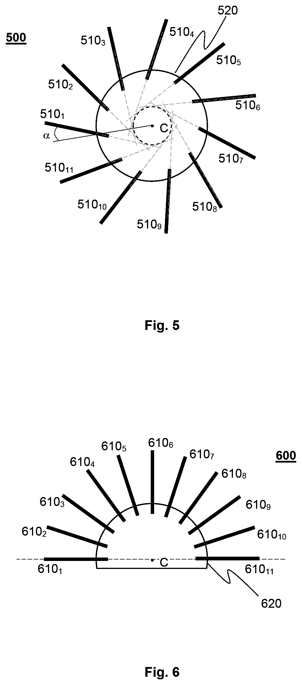
[0040]If another algorithm than modal beamforming is used, it may however be appropriate to arrange the directional microphones differently, namely not exactly radially but slightly rotated or displaced, respectively. This makes the overall arrangement smaller, without reducing the length of the individual directional microphones or the diameter of the circle of microphone capsules. FIG. 5 shows a microphone array 500 in a third embodiment, where each of the eleven microphones 5101, . . . , 51011 is rotated through an angle α with their microphone capsules being arranged on a circle 520. The algorithm used must consider this rotation, wherein very small angles can be neglected.

fourth embodiment

[0041]Moreover, it may make sense for certain applications to arrange the directional microphones on a segment of a circle that has a certain angle, e.g., if only low levels of disturbing noise from the rear are to be expected. However, the disadvantage of a segmental arrangement as compared to a circular arrangement is that for a positioning near the edge, ambient noise from directions in which no directional microphone is pointed cannot be well suppressed. This problem can be compensated partially by making the segment larger than the region to be observed. FIG. 6 shows a microphone array 600 in a fourth embodiment, wherein again eleven directional microphones 6101, . . . , 61011 are evenly distributed over a semicircle. For a central alignment near 0° corresponding to the microphone 6106 this arrangement works well. Also for a region of e.g. ±45° around the central alignment an acceptable result may be achievable. Correspondingly, a microphone array of a form as shown in FIG. 6 i...


PUM


Abstract

For certain application cases, such as e.g., in a sports stadium, a microphone array having a particularly high directivity in the vertical direction and a high, yet in wide limits adjustable directivity in horizontal direction is provided. The microphone array has a plurality of microphones whose output signals are combined into at least one common output signal. The microphones are directional microphones with a preferred direction of high sensitivity and arranged substantially in one plane on a circle or segment of a circle, such that each microphone has a different direction of high directivity. For each of the microphones, the preferred direction of high sensitivity is substantially orthogonal to the circle or segment of the circle. A common output signal of the microphone array is obtained by beamforming. The microphone array has an adjustable preferred direction of high sensitivity, wherein the common output signal comprises the sound recorded from this adjustable direction.

Description

CROSS-REFERENCE TO RELATED APPLICATIONS[0001]This application is the National Stage entry under 35 U.S.C. § 371 of International Application No. PCT / EP2019 / 061529 filed May 6, 2019, published as Publication No. WO 2019 / 211487 on Nov. 7, 2019, which claims benefit of foreign priority of German Patent Application No. 10 2018 110 759.5, filed on May 4, 2018, the entireties of which are herein incorporated by reference.FIELD OF DISCLOSURE[0002]The invention relates to a microphone array.BACKGROUND[0003]For sound recordings in large sports facilities, the acoustic events on the field may be particularly interesting for an immersive playback, such as noise from the ball, the bat or racket and so forth as well as conversations of the players, umpire or referee, trainers and so forth. Due to the amount of ambient noise, it is difficult to achieve a good sound quality and speech intelligibility. This has to do with the fact that microphones often have to be positioned on the edge of the fiel...

Claims


Application Information

Patent Timeline
Patent Type & Authority Patents(United States)
IPC IPC(8): H04R1/32H04R3/00
CPCH04R1/326H04R3/005H04R2201/401H04R2203/12H04R2430/23H04R1/406H04R2430/20
Inventor KRÜGER, ALEXANDER
Owner SENNHEISER ELECTRONICS GMBH & CO KG
Learn More