
Bar arrangement for a machine for the production of a fibrous web

a technology of fibrous webs and machines, which is applied in the direction of machine wet ends, papermaking, textiles and papermaking, etc., to achieve the effects of simple and inexpensive construction, quick change out, and good gliding properties

Inactive Publication Date: 2012-05-01
VOITH PATENT GMBH
View PDF12 Cites 0 Cited by
  • Summary
  • Abstract
  • Description
  • Claims
  • Application Information

AI Technical Summary

Benefits of technology

The present invention provides a bar arrangement with a return mechanism that allows for a smooth and reliable return of the movable bar from its operating position to its inoperative position. The return mechanism includes a guided part with a slanted ascending surface that is connected detachably to the movable bar and a fixed guide arm with a slanted guide surface that guides the movable bar. The slanted ascending surface has a slant angle between 5 to 60 degrees, preferably 20 to 45 degrees, especially -25 to -35 degrees. The guided part can be a separate part or an integral part of the movable bar. The fixed guide arm is shorter than the other fixed guide arm, and the ascending side of the movable bar is the side where the return mechanism is located. The invention provides a process-reliable, cost-effective, and reproducible solution for the return of the movable bar.

Problems solved by technology

However, this necessitates a long lateral displacement path of the movable bar.

Method used


Image

  • Bar arrangement for a machine for the production of a fibrous web
  • Bar arrangement for a machine for the production of a fibrous web
  • Bar arrangement for a machine for the production of a fibrous web

Examples


Embodiment Construction

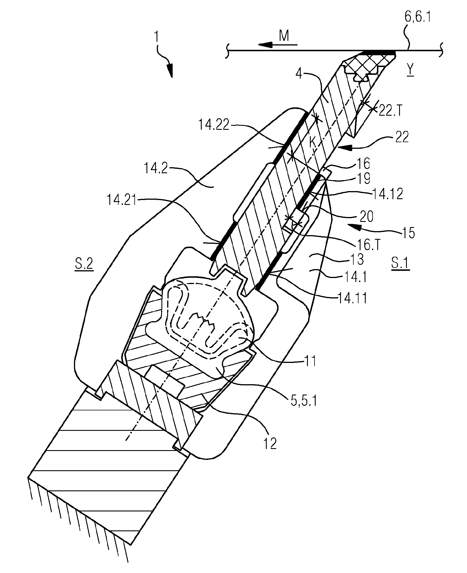
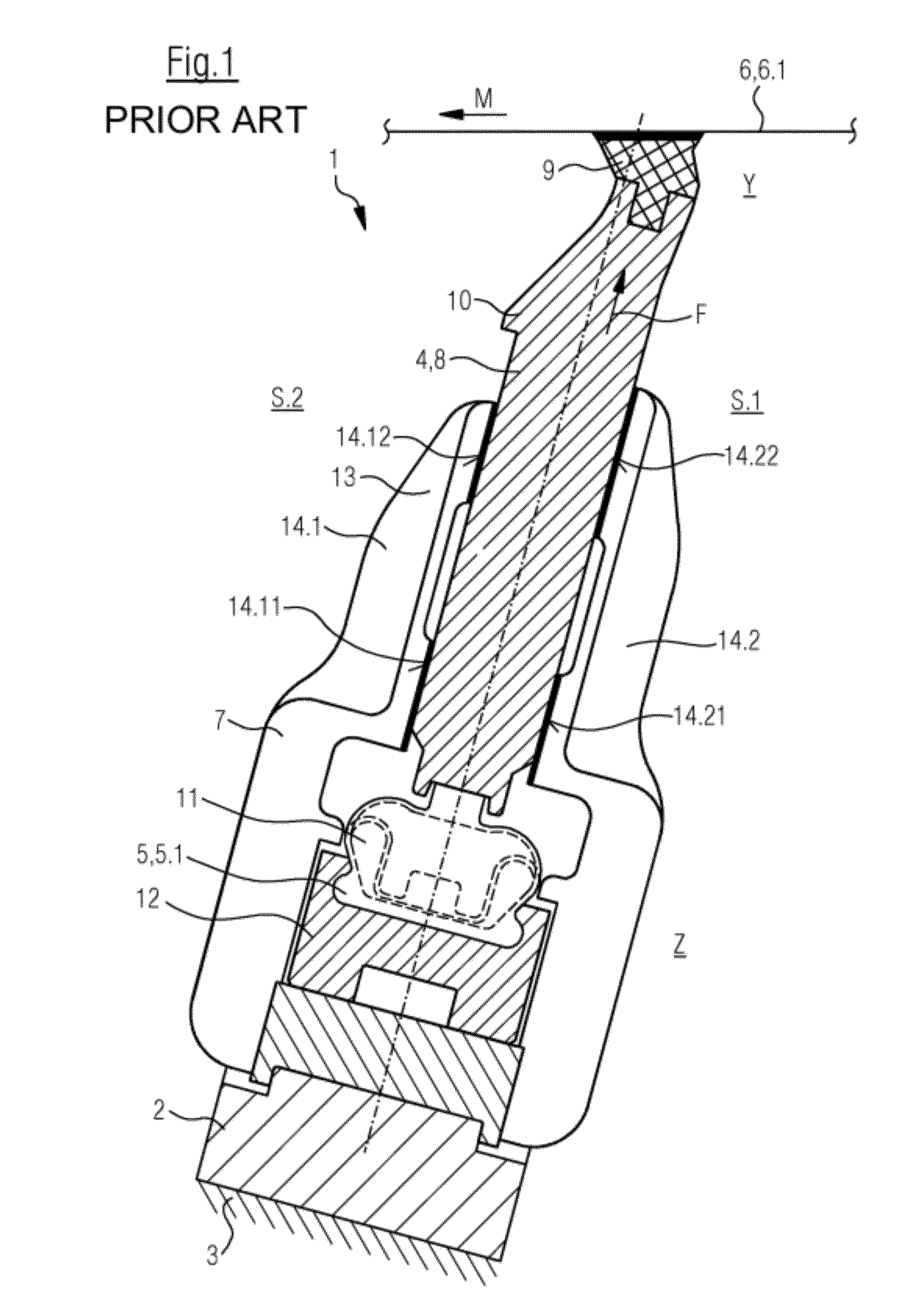
[0041]Referring now to the drawings, and more particularly to FIG. 1, there is shown a schematic cross sectional view of a bar arrangement 1 for a machine for the production of a fibrous web which is not illustrated in further detail in this drawing. The fibrous web may in particular be a paper, cardboard or tissue web.

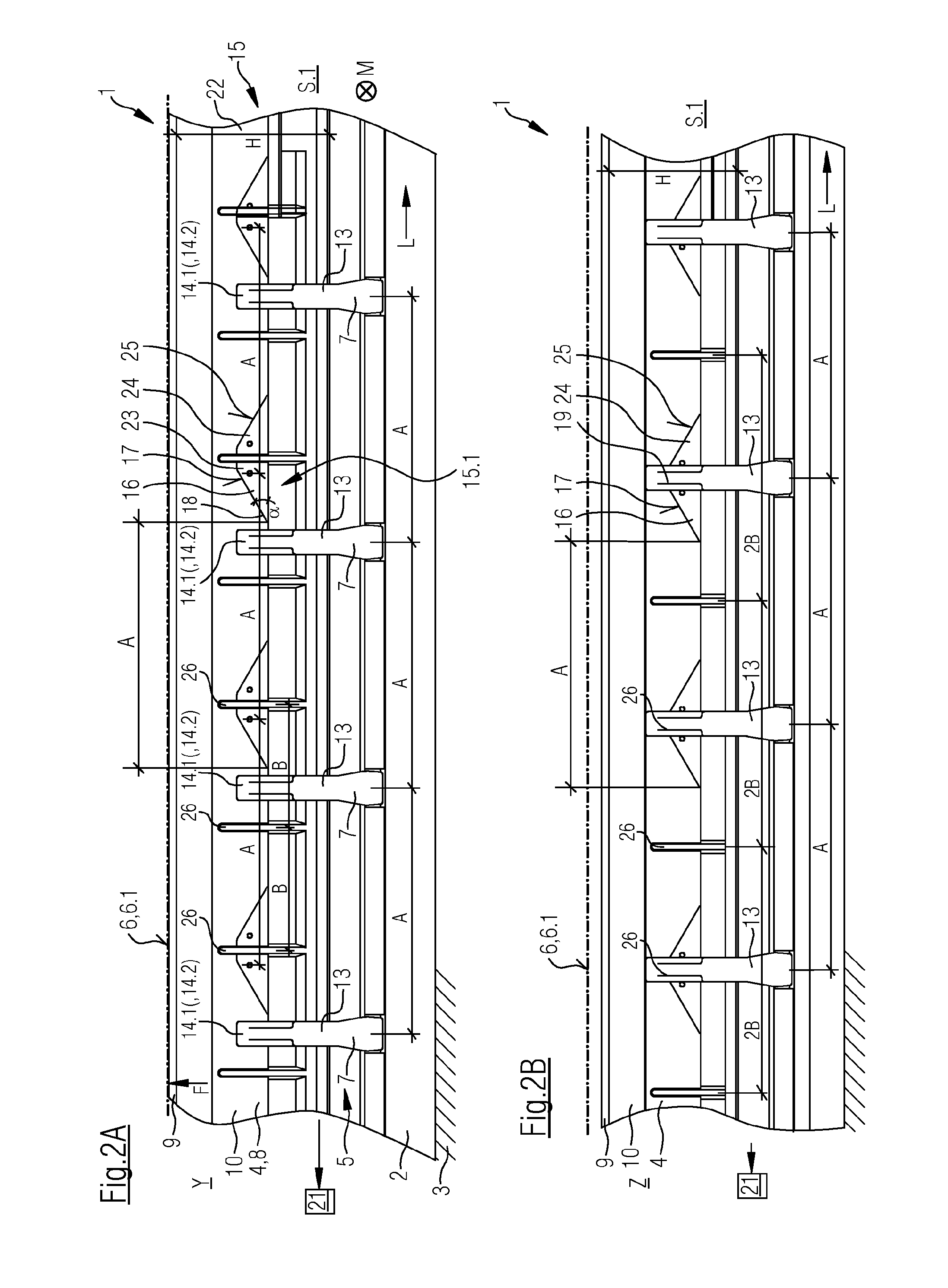
[0042]Bar arrangement 1 extends transversely to machine direction M (arrow) and includes a fixed structure 2 which is mounted directly or indirectly to a machine frame 3 (which is merely indicated). It also includes a movable bar 4 which is connected indirectly with fixed structure 2 and is movable in reference to this by preferably a controllable / adjustable operating device 5 at least between a depicted operating position Y in which movable bar 4 can be pressed against an element 6 by means of a selectable contact force F (arrow) and an inoperative position Z which is not shown but which is known to the expert. Inoperative position Z can here be consistent with the s...


PUM


Abstract

The invention relates to a bar arrangement for a machine for producing a fibrous web. The bar arrangement according to the invention is characterized by at least one restoring mechanism for bringing the mobile bar from the operating position into the rest position. The at least one restoring mechanism comprises at least one guided piece arranged on the mobile bar on the exterior and alongside thereof, said piece having an inclined contact surface the incline of which is directed at an angle (α) in the range of 5 to 60°, preferably of 20 to 45°, especially of 25 to 35°, relative to the longitudinal direction of the mobile bar, at least one guiding piece on the interior of the C-shaped guiding unit, which has a preferably inclined guide surface that can be brought in contact with the inclined contact surface of the guided piece arranged on the exterior and alongside thereof when the mobile bar is brought from the operating position into the rest position, and at least one displacement device for displacing the mobile bar in its longitudinal direction which acts upon the mobile bar, preferably the face thereof, and which can preferably be controlled / regulated.

Description

CROSS REFERENCE TO RELATED APPLICATIONS[0001]This is a continuation of PCT application No. PCT / EP2009 / 058088, entitled “BAR ARRANGEMENT FOR A MACHINE FOR PRODUCING A FIBROUS WEB”, filed Jun. 29, 2009, which is incorporated herein by reference.BACKGROUND OF THE INVENTION[0002]1. Field of the Invention[0003]The invention relates to a bar arrangement for a machine for the production of a fibrous web, especially a paper, cardboard or tissue web, which extends transversely to the machine direction and which comprises at least one fixed structure which is mounted directly or indirectly to a frame of the machine; at least one movable bar which is connected preferably indirectly with the fixed structure, relative to which it is preferably movable by means of a controllable / adjustable actuation device, at least between an inoperative position and an operating position in which the movable bar can be pressed against an element by means of a selectable contact force; and at least one fixed gui...

Claims


Application Information

Patent Timeline
Patent Type & Authority Patents(United States)
IPC IPC(8): D21G9/00
CPCD21F1/486
Inventor SCHMIDT, FRANKMULLER, ANSGARGRABSCHEID, JOACHIM
Owner VOITH PATENT GMBH
Learn More