Vehicle rear-view mirror

a rearview mirror and vehicle technology, applied in the field of vehicle rearview mirrors, can solve the problem of unnoticeable warning symbols, and achieve the effects of reducing the number of components, eliminating the use of light diffusion plates, and facilitating assembly

Active Publication Date: 2012-05-01
MURAKAMI CORP
View PDF10 Cites 45 Cited by
  • Summary
  • Abstract
  • Description
  • Claims
  • Application Information

AI Technical Summary

Benefits of technology

[0009]According to the present invention, since the light-orienting tube is arranged so that it is inclined in the direction toward the driver's viewpoint, when a warning is indicated, it is easy to see from the driver and is hard to see from following vehicles and vehicles on the adjacent lanes. Also, since the light source and the indication mask are arranged outside or inside the light-orienting tube at the back portion of the tube, when no warning is indicated, the warning symbol is unnoticeable. Also, when no warning is indicated, the indicator (indication part) becomes a part of the mirror surface, causing no discontinuities in the image of the rear view reflected in the mirror surface.
[0010]In the present invention, the angle between the axis of the light-orienting tube and the surface of the mirror element can be, for example, 30° to 80°. The area of the front end-side opening of the light-orienting tube in the direction perpendicular to the axis can be larger than the area of the rear end-side opening in the direction perpendicular to the axis. This makes it possible for the driver to see the indication even though the position of the driver's viewpoint moves in some degree. The front shape of the opening in the mask member is unnoticeable if it is made to be, for example, a simple geometric shape, such as a circle, an oval or an elliptic, which can avoid obtrusiveness even if the opening is seen through in some degree when no warning is indicated. If the light-orienting tube is molded integrally with the mask member or a mirror holder arranged behind the mask member, the number of components can be reduced, easy assembly can be made possible.
[0011]Also, in the present invention, it is possible that: the mirror element has the semi-transmissive reflective film formed of a dielectric multilayer film, the mirror element has a characteristic that exhibits one reflection peak in the visible light range; and indication light entering the mirror element has a light intensity peak in a band in which the transmittance of the mirror element is higher than the reflectance of the mirror element. This makes it possible to provide both visibility of the rear-area image and that of the indication. More specifically, the reflection color of the mirror element may be a bluish color, and the indication light entering the mirror element may be red.
[0012]Also, in the present invention, when the light source is an LED (light-emitting diode), it is possible to indicate the entire warning symbol with a uniform brightness by means of arranging a light diffusion plate between the light source and the indication mask. Also, when the light source is a white light (white lamp), it is possible to arrange a band-pass filter, which allows light in a particular band to pass through, and a light diffusion plate between the light source and the indication mask. Also, when the light source is an EL (electroluminescence) element, since the EL element itself can indicate the entire warning symbol with a uniform brightness, it is possible to eliminate the use of the light diffusion plate. Also, since the EL element can emit light in a particular band, it is also possible to eliminate the use of the band-pass filter.

Problems solved by technology

Also, since the light source and the indication mask are arranged outside or inside the light-orienting tube at the back portion of the tube, when no warning is indicated, the warning symbol is unnoticeable.

Method used


Image

  • Vehicle rear-view mirror
  • Vehicle rear-view mirror
  • Vehicle rear-view mirror

Examples


embodiment 1

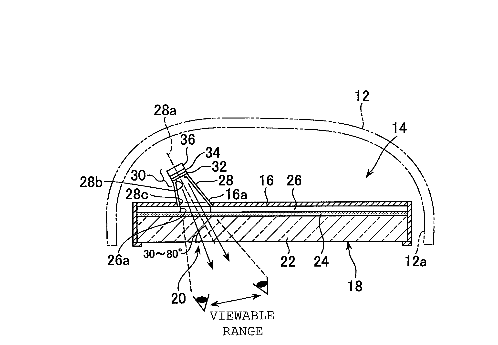
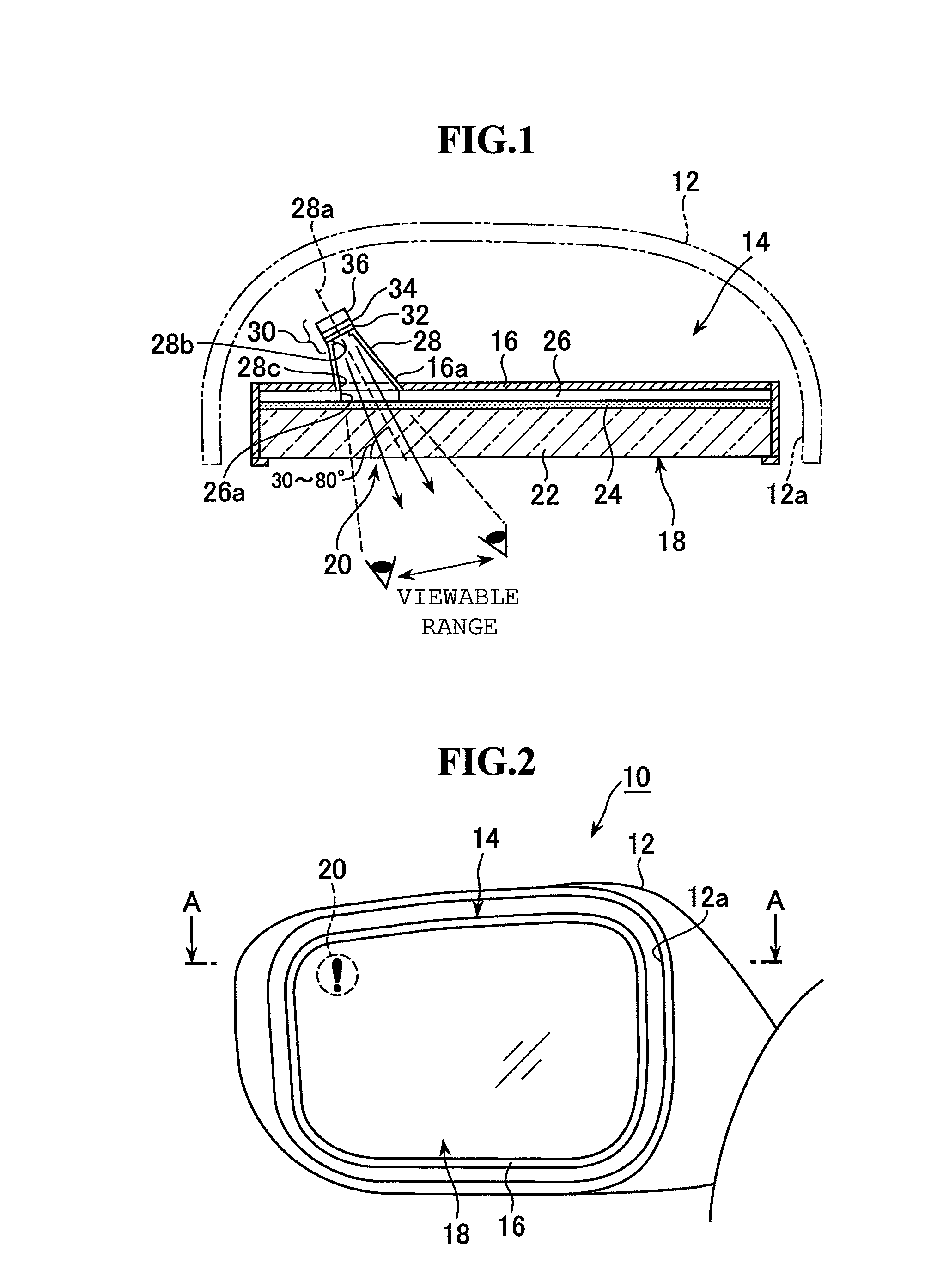
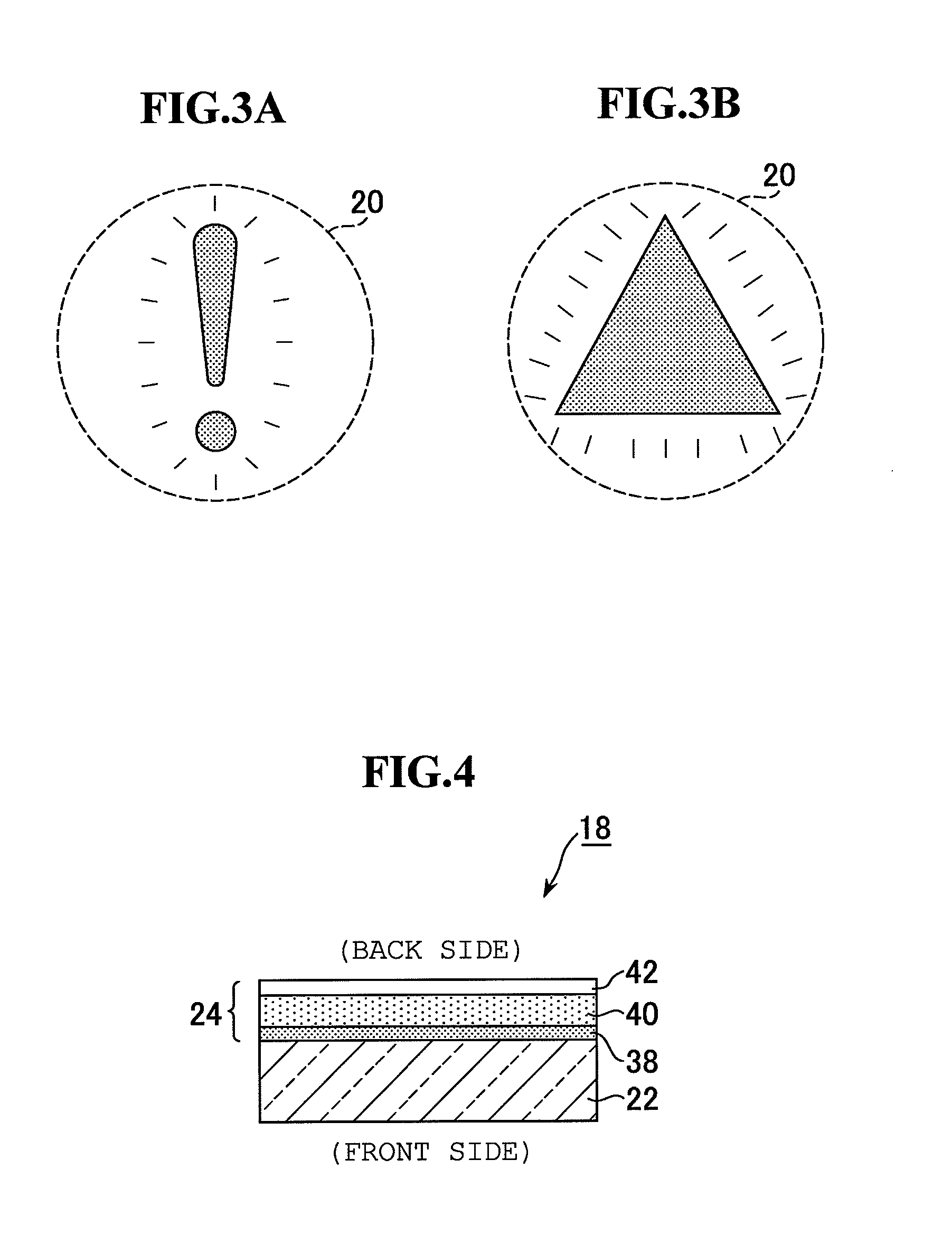
[0026 of the Present Invention is Shown in FIG. 1. A mirror element 18 is configured by forming a semi-transmissive reflective film 24 formed of a dielectric multilayer film on the entire back surface of a transparent glass substrate 22. At the entire region behind the mirror element 18 excluding an opening 26a, which will be described later, a dark color mask member 26 is arranged. The mask member 26 is intended to prevent the inside of the mirror from being seen through from outside, and can be formed by, for example, a resin plate, a resin film or a coating material (paint), all of which are of dark colors (for example, black). The mask member 26 and the mirror element 18 are put into the front portion of the mirror holder 16 formed of, for example, a dark color (for example, black) resin, thereby the mirror body 14 having an integral structure. When the mask member 26 is formed of a resin plate or a resin film, the mirror element 18 and the mask member 26 can be attached to each...

embodiment 2

[0031 of the Present Invention is Shown in FIG. 6. This is formed by altering the structure of the light-orienting tube in Embodiment 1 (FIG. 1). The parts in common to those in FIG. 1 are provided with the same reference numerals. Here, a light-orienting tube 44 is connected to a mirror holder 16. The light-orienting tube 44 is of a dark color (for example, black) on the inner side. It is also possible to form the mirror holder 16 and a light-orienting tube 44 as an integrally-molded product using the same resin material. The light-orienting tube 44 bulges outwardly at an intermediate portion in the direction of the tube axis 44a, and the cross section of the light-orienting tube 44 cut by a plane passing through the axis 44a is hexagonal as shown in FIG. 6. The cross section of the light-orienting tube 44 in the direction perpendicular to the axis 44a is circular. A front end-side opening 44c of the light-orienting tube 44 has a horizontally-long oval shape having the same dimensi...


PUM


Abstract

To provide a vehicle rear-view mirror equipped with a display device, configured so that: a warning indication is easy to see from the driver and is hard to see from following vehicles and vehicles on the adjacent lanes; and when no warning is indicated, no discontinuities occur in the rear-area image reflected in the mirror and the warning symbol is unnoticeable. A mirror element 18 is configured by forming a semi-transmissive reflective film 24 or 56 formed of a dielectric multilayer film on the back or front surface of a transparent glass substrate 22. A dark color mask member 26 is arranged on the back surface of the mirror element 18. An opening 26a is formed on the mask member 26. A light-orienting tube 28 is arranged in such a manner that it protrudes in the backward direction of the mask member 26 so as to surround the opening 26a. The tube axis 28a of the light-orienting tube 28 is inclined in the direction toward the driver's viewpoint. An indication mask 32, a light diffusion plate 34 and an LED 36 are arranged as an indication light-emitting portion 30 by depositing them in this order on a rear end-side opening 28b of the light-orienting tube 28.

Description

[0001]The disclosure of Japanese Patent Application No. JP2007-255075 filed on Sep. 28, 2007 including the specification, drawing and abstract is incorporated herein by reference in its entirety.BACKGROUND OF THE INVENTION[0002]1. Field of the Invention[0003]The present invention relates to a vehicle rear-view mirror equipped with a display device that issues a warning to the driver, configured so that: when a warning is indicated, it is easy to see from the driver and is hard to see from following vehicles and vehicles on the adjacent lanes; and when no warning is indicated, no discontinuities occur in the image of the rear view and the warning symbols are unnoticeable.[0004]2. Description of the Related Art[0005]U.S. Pat. Nos. 5,313,335 and 6,099,154 each disclose a vehicle rear-view mirror equipped with a display device that emits warning light to the driver. U.S. Pat. No. 5,313,335 discloses a mirror having an indicator formed at a part of a surface of a mirror element, the indi...

Claims


Application Information

Patent Timeline
Patent Type & Authority Patents(United States)
IPC IPC(8): B60R25/10B60Q1/34B60Q1/32B60Q1/50B60R1/06B60R1/12
CPCB60Q1/2665B60R1/1207B60R2001/1215B60R2300/8053
Inventor NAKAMURA, MASATOSHITAKAYANAGI, SHINYABANDOU, ATSUNORIMASUDA, YOSHIFUMI
Owner MURAKAMI CORP
Why Eureka
Try Eureka