
Method for (semi-) automatic dental implant planning

a semi-automatic and dental implant technology, applied in dental surgery, instruments, teeth capping, etc., can solve the problems of inability to provide automatic or semi-automated assistance in determining the optimal position of implants from a biomechanical, functional or aesthetic point of view, and no longer valid standard solutions. , to achieve the effect of saving tim

Active Publication Date: 2012-05-01
DENTSPLY IMPLANTS NV
View PDF9 Cites 33 Cited by
  • Summary
  • Abstract
  • Description
  • Claims
  • Application Information

AI Technical Summary

Benefits of technology

[0013]A first object of the present invention is to provide improved methods for (semi-) automatic dental implant planning based on biomechanical, aesthetic and functional consideration, using volume data, e.g. from a volumetric scan. An advantage of the present invention is to overcome at least some of the disadvantages of the prior art.
[0063]A significant advantage of the present invention is that clinicians are substantially aided in deciding on a treatment plan by having unambiguous guidelines implemented on a patient specific basis. The invention also constitutes a considerable saving in time given that a lot of criteria can be verified in a fraction of the time of what would be required if done manually.

Problems solved by technology

The classic solution is no longer valid when evolving towards immediate loading of the implant.
Immediate loading of the implants requires a flawless planning and precise surgical transfer.
Although the current computer programs for dental implant planning all visualize the information necessary to simulate different implant treatments and all offer a range evaluation tools, none provide automated or semi-automated assistance in determining the optimal position of the implants from a biomechanical, functional or aesthetic point of view.

Method used


Image

  • Method for (semi-) automatic dental implant planning
  • Method for (semi-) automatic dental implant planning
  • Method for (semi-) automatic dental implant planning

Examples


Embodiment Construction

[0136]The present invention will be described with respect to particular embodiments and with reference to certain drawings but the invention is not limited thereto but only by the claims.

Finding Optimal Implant Positions

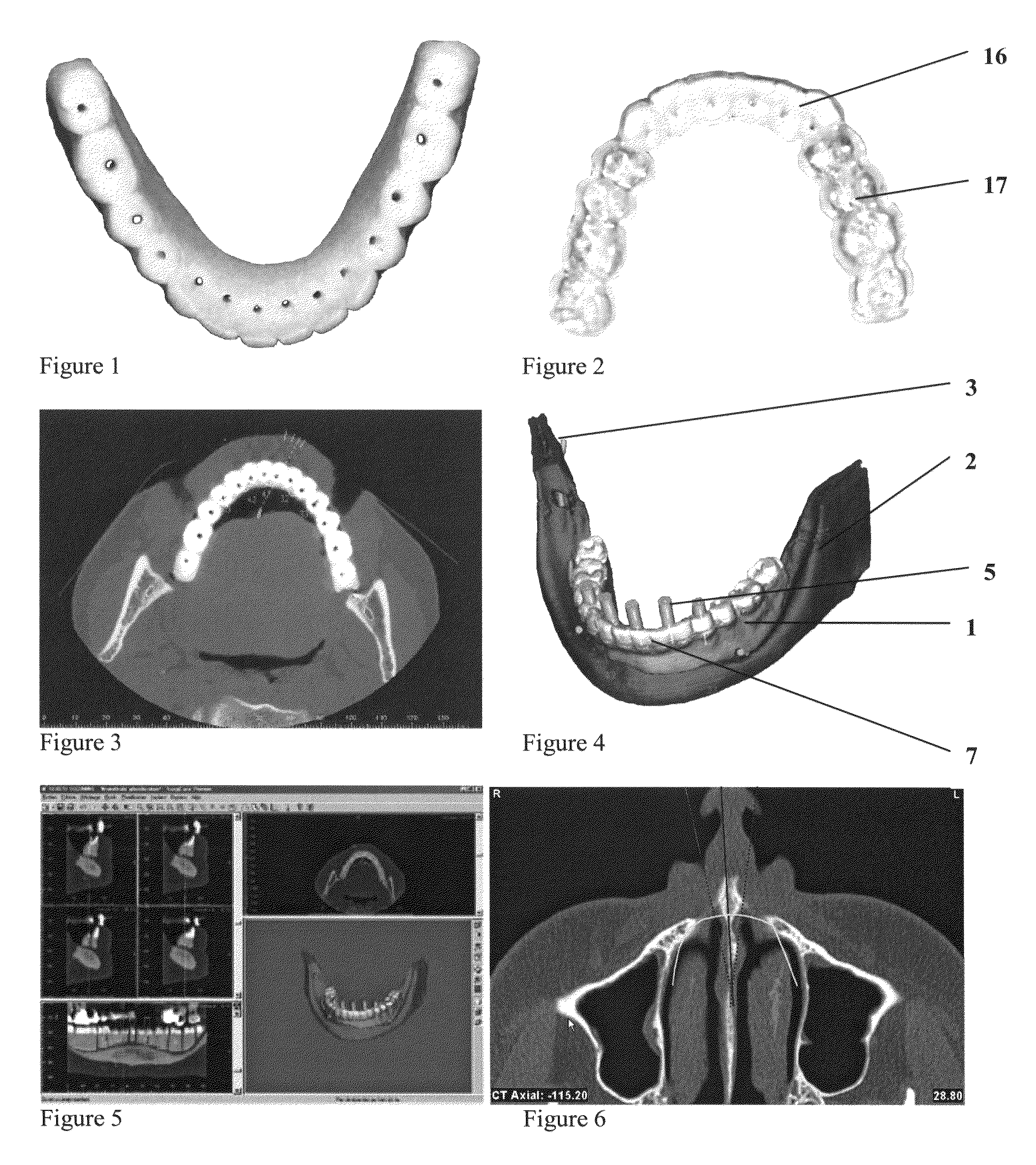
[0137]According to a preferred embodiment of the invention a three-dimensional representation of the desired tooth setup (1) and the jaw (2) and any nerves (3) or blood vessels is required and obtained (see FIG. 4). The methods for preparing information for automated or semi-automated dental implant planning from image information relating to the jaw of a patient as subject of the present invention are to be understood as computer based methods for preparing information for automated or semi-automated dental implant planning from image information relating to the jaw of a patient.

[0138]A schematic overview of a method according to the present invention is shown in FIG. 28. The steps shown in this flow will be described in more detail below.

[0139]The method starts wh...


PUM


Abstract

A method and system for (semi-) automatic dental implant planning (A) is described including (a) means for creating 3D models of a tooth setup (b) and / or means for creating 3D models of parts of the jaw, (c) means for detecting zones in the jaw where implants can (or optionally cannot be placed), (d) means for detecting restorative elements in the tooth setup, (e) means for determining candidate implant dimensions, positions, orientations and configurations, (f) means for obtaining implant plans, (g) means for comparing implant plans to each other or to given criteria, (h) means for selecting or improving an implant plan.

Description

FIELD OF THE INVENTION[0001]The present invention relates to methods and apparatus for (semi-) automatic dental implant planning, e.g. based on biomechanical, aesthetic and / or functional considerations as well as to computer methods, computer systems and software for implementing the methods.TECHNICAL BACKGROUND[0002]A dental implant is an artificial tooth root that periodontists place into the jaw to hold a replacement tooth or to support a replacement prosthesis. Treatment with dental implants is widely accepted and holds a number of advantages over other techniques such as removable partial dentures, bridges or loose prostheses. Dental implants allow reconstruction of the dentition without the need to sacrifice healthy neighbouring teeth. The loads transferred via the implants stimulate the bone, preventing bone resorption and limiting recession of the gums around the replaced tooth elements and resulting in a more aesthetic reconstruction. Treatment with implants also provides a...

Claims


Application Information

Patent Timeline
Patent Type & Authority Patents(United States)
IPC IPC(8): G06K9/00A61C8/00A61C13/00
CPCA61C1/084A61C8/0022A61B6/506A61C13/0004A61C8/0034A61C13/00A61C13/34A61C19/04A61C8/00G16H20/40
Inventor GLOR, FADIVRIELINCK, LUC
Owner DENTSPLY IMPLANTS NV
Learn More