
Feeding device and image recording apparatus with the feeding device

a technology of feeding device and image recording apparatus, which is applied in the direction of pile separation, article separation, transportation and packaging, etc., can solve the problem of curling at the end of the sheet that is switched and returned

Active Publication Date: 2012-05-08
BROTHER KOGYO KK
View PDF4 Cites 39 Cited by
  • Summary
  • Abstract
  • Description
  • Claims
  • Application Information

AI Technical Summary

Benefits of technology

[0007]It is an object of the present invention to provide a feeding device and an image recording apparatus with the feeding device, which are capable of arranging the shape of the end portion of the sheet into the more desirable shape.

Problems solved by technology

Such a feeding device has a problem in that an end of the sheet that is switched and returned tends to curl.

Method used


Image

  • Feeding device and image recording apparatus with the feeding device
  • Feeding device and image recording apparatus with the feeding device
  • Feeding device and image recording apparatus with the feeding device

Examples


Embodiment Construction

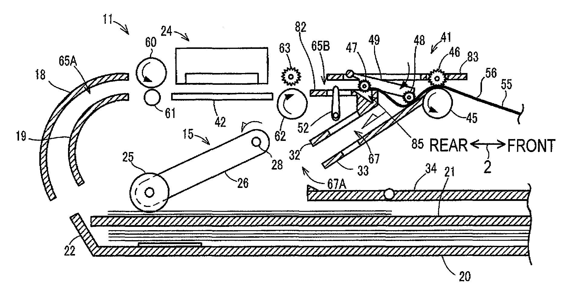
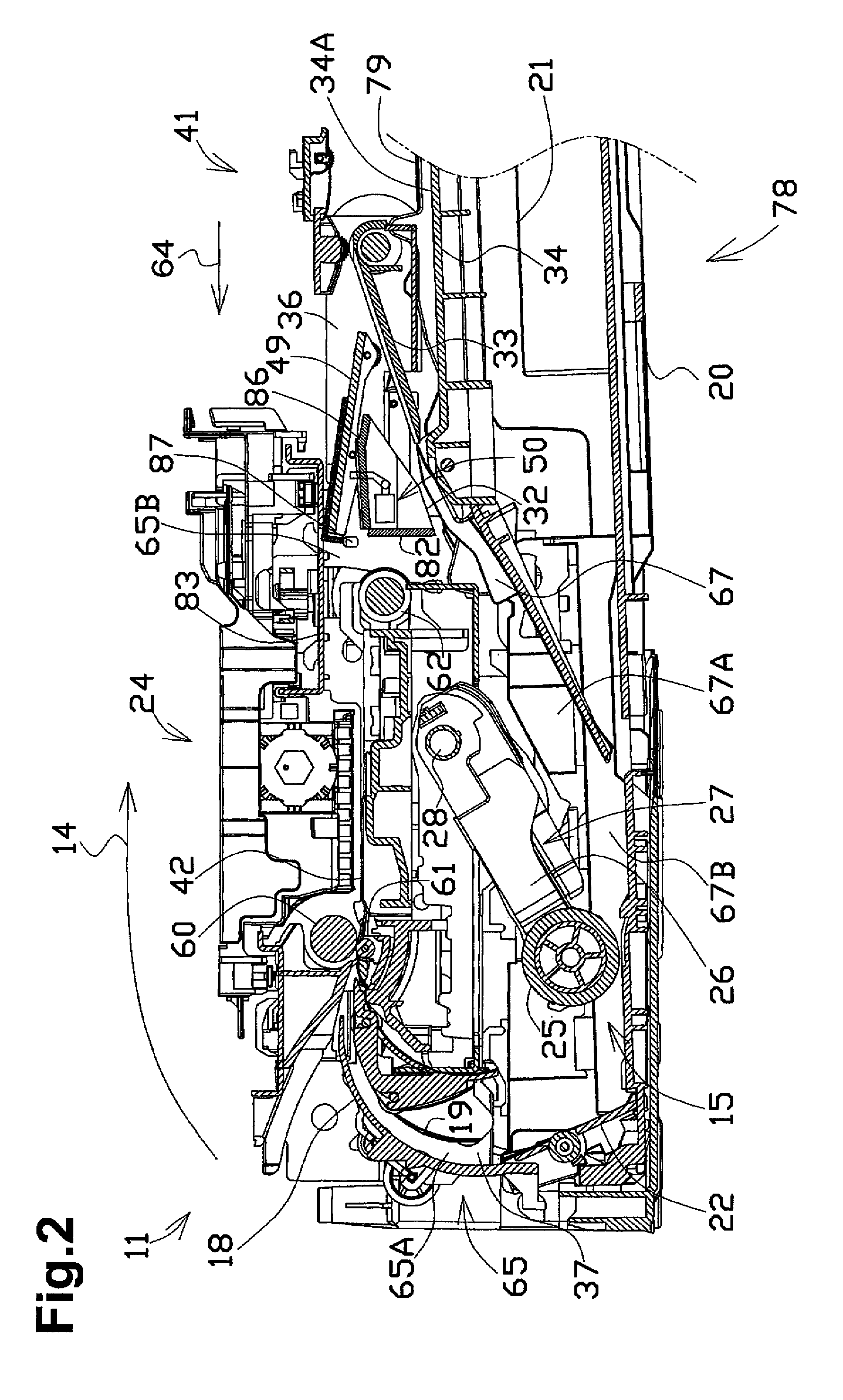
[0020]Referring to the drawings, preferred embodiments of the present invention will be described below. Note that the embodiments described below are merely examples of the present invention, and the embodiments of the present invention can of course be modified within the scope not changing the gist of the present invention.

[0021][Outline of the Multifunction Device]

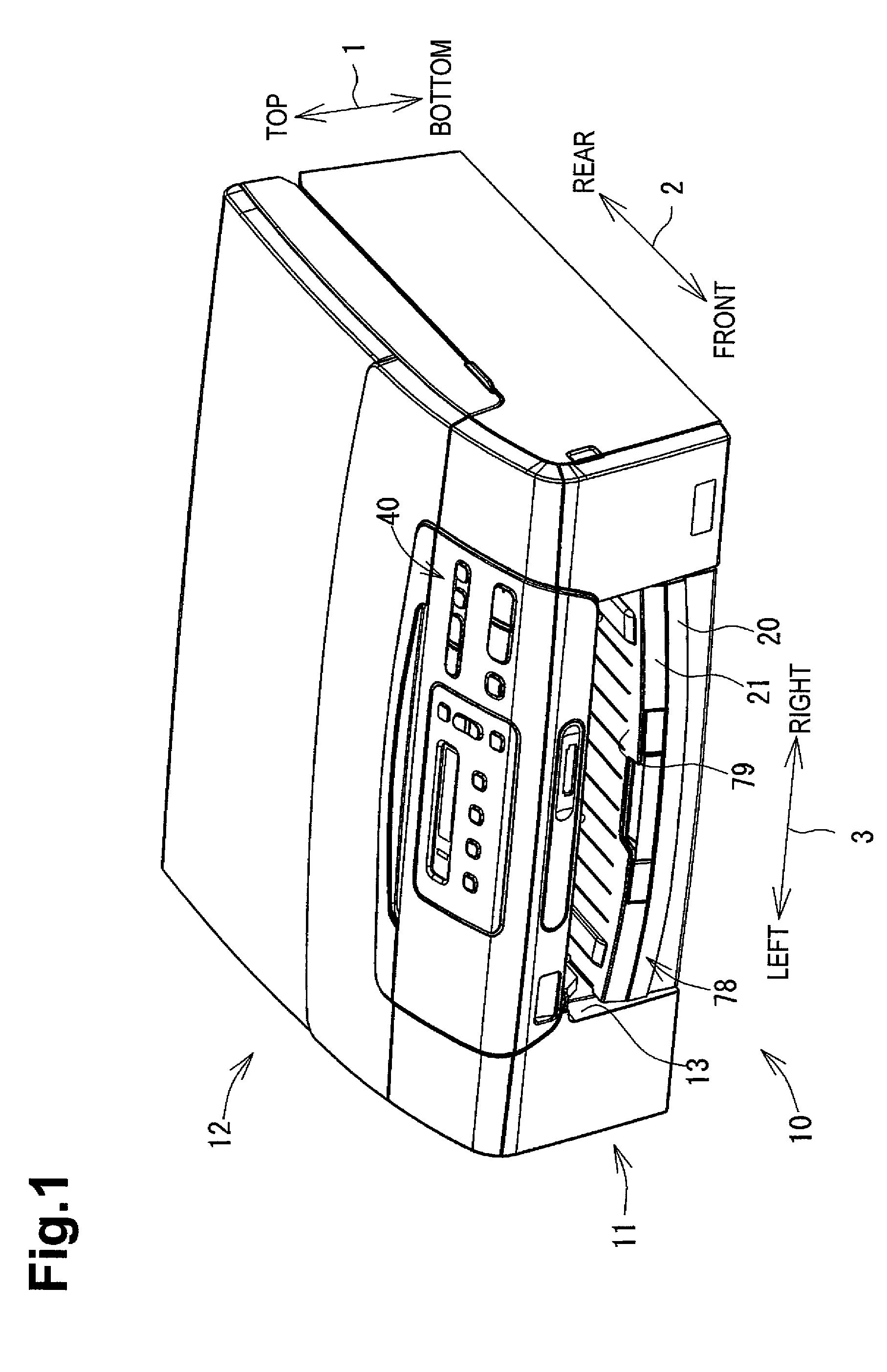
[0022]FIG. 1 is a perspective view showing the exterior of a multifunction device 10 according to an embodiment of the present invention. In the following description, a top-bottom direction 1 is defined based on a state in which the multifunction device 10 is installed in a usable state (the state shown in FIG. 1), a front-rear direction 2 is defined such that the side having an operation panel 40 is the near side (front), and a left-right direction 3 is defined by viewing the multifunction device 10 from the near side (front).

[0023]The multifunction device 10 has a substantially thin rectangular parallelepiped shape,...


PUM

PropertyMeasurementUnit
pressing forceaaaaaaaaaa
reaction forceaaaaaaaaaa
weightaaaaaaaaaa

Abstract

A feeding device has a conveying roller that rotates in a forward direction and a reverse direction, to selectively convey a sheet in a conveying direction and a reverse conveying direction. A particular guide member is positioned on an upstream side, guides the conveyed sheet toward the conveying roller, and has a stopper that contacts an end portion of the sheet, thereby stopping movement of the sheet in the reverse conveying direction. A control unit causes the conveying roller to rotate the conveying roller in the forward direction, such that the sheet is conveyed to a predetermined position, then to rotate the conveying roller in the reverse direction, wherein the end portion of the sheet contacts the stopper while the conveying roller rotates in the reverse direction, and then to again rotate the conveying roller in the forward direction, such that the sheet is conveyed toward the conveying roller.

Description

CROSS REFERENCE TO RELATED APPLICATION[0001]The present application claims priority from Japanese Patent Application No. 2009-054244, which was filed on Mar. 6, 2009, the disclosure of which is incorporated herein by reference in its entirety.BACKGROUND OF THE INVENTION[0002]1. Field of the Invention[0003]The present invention relates to a feeding device and an image recording apparatus having a mechanism for sending a sheet.[0004]2. Description of the Related Art[0005]Conventionally, feeding devices capable of switching the traveling direction of the sheet and returning the sheet to a conveying path are known. Such a feeding device has a problem in that an end of the sheet that is switched and returned tends to curl.[0006]To solve this problem, feeding devices which prevent the sheet from curling by employing a configuration in which a plurality of conveying rollers each positioned in a comb-like arrangement press and convey the sheet are known. In such a feeding device, when the s...

Claims


Application Information

Patent Timeline
Patent Type & Authority Patents(United States)
IPC IPC(8): B65H5/00B65H29/00
CPCB41J3/60B41J11/0005B41J13/0045B65H5/38B65H15/00H04N1/00572H04N1/00578H04N1/0058H04N1/00618B65H2301/33312B65H2301/512125B65H2402/46B65H2404/61B65H2404/72B65H2801/06H04N2201/0082H04N2201/0093Y10S271/902
Inventor TANAHASHI, NAOKAZU
Owner BROTHER KOGYO KK
Learn More