Fixing belt, base element for fixing belt, fixing device, image forming apparatus and method for producing base element

a technology of fixing belts and fixing devices, which is applied in the direction of electrographic processes, instruments, other domestic objects, etc., can solve the problems of large power consumption, limited thickness of elastic layers, and disadvantages such as electrostatic off-set, so as to prevent the breakage of the fixing belt at the thinned portion, reduce the durability of the fixing belt, and reduce the thickness of the elastic layer

Active Publication Date: 2013-09-24
RICOH KK
View PDF44 Cites 0 Cited by
  • Summary
  • Abstract
  • Description
  • Claims
  • Application Information

AI Technical Summary

Benefits of technology

[0032]The base element requires a sheet to be used as a raw material. If an endless belt formed in a cylindrical shape is used instead of the sheet, advantageous effects of the present invention are not provided because a high-accuracy and expensive die are required for producing the belt, causing high cost for producing the base element.
[0033]It is necessary that the sheet be made of a heat-resistant resin, particularly polyimide, so that sufficient heat resistance of an elastic layer of a silicon rubber, a fluorine rubber or the like to produce a fixing belt can be obtained.
[0034]The used polyimide sheet is in a thickness of 50 μm to 125 μm as used for a conventional fixing belt. If the thickness of the sheet is more than 125 μm, lack of flexibility occurs and if it is less than 50 μm, lack of strength of the fixing belt occurs so that less durability of the fixing belt is provided.
[0035]The above polyimide sheet is cut to form a sheet so that a fixing belt in a desirable shape can be obtained, and then thinned portions are provided on opposite surfaces of opposite end portions of the sheet.
[0036]Each of the thinned portions may be formed in a stepped shape or a tapered shape. In the latter case, the opposite end portions may be processed such that the thickness of the thinned portion is gradually thinned approaching an end of the sheet. Since the tapered thinned portion is continuously thinned, breakage of the fixing belt at the thinned portion can be prevented unlike in the former case where the fixing belt is broken at a stepped portion. That is to say, the stepped thinned portions formed by a cutting process can be prevented from leading to bending or reduction of the durability of the fixing belt due to a local stress concentration, which may occur in the former case.
[0037]It is preferable that a low-cost grinding process by a grinding machine be performed to form the above thinned portion, instead of a high-cost half-etching process with a UV laser. It is possible to form the stepped thinned portion by cutting with an end milling using a general-use milling machine. In this case, a variation of the thickness is greater than that in the case of the grinding process; however, it is advantageous that the cutting process be performed in a short time.

Problems solved by technology

However, in the fixing roller with the above-mentioned elastic layer, a thickness of the elastic layer is limited within a certain constant value to prevent a long warming up time.
However, since it takes a long time to heat the thermal fixing roller up to the desirable temperature, there is a problem in that a large power consumption is required.
In the above-mentioned fixing device in the fixing belt type electrophotographic device, the fixing belt is charged due to friction occurring when a transferred paper passes between the fixing belt and the pressure roller, so that a disadvantage such as an electrostatic off-set occurs.
However, since a large number of dies are required and the inner surface of the die is required to be smoothed uniformly in order to allow the obtained endless belt to be separated from the die, these techniques involve high cost because of the dies.
Since the above-mentioned fixing device includes an expensive fixing belt, there is a need to decrease the production cost of the fixing belt.
However, the technique does not achieve a charging prevention effect if the technique is applied to the fixing belt.

Method used


Image

  • Fixing belt, base element for fixing belt, fixing device, image forming apparatus and method for producing base element
  • Fixing belt, base element for fixing belt, fixing device, image forming apparatus and method for producing base element
  • Fixing belt, base element for fixing belt, fixing device, image forming apparatus and method for producing base element

Examples


examples

[0064]As mentioned below, embodiments of the present invention are described. However, the present invention is not limited to the embodiments.

[0065][Fixing Belt A1]

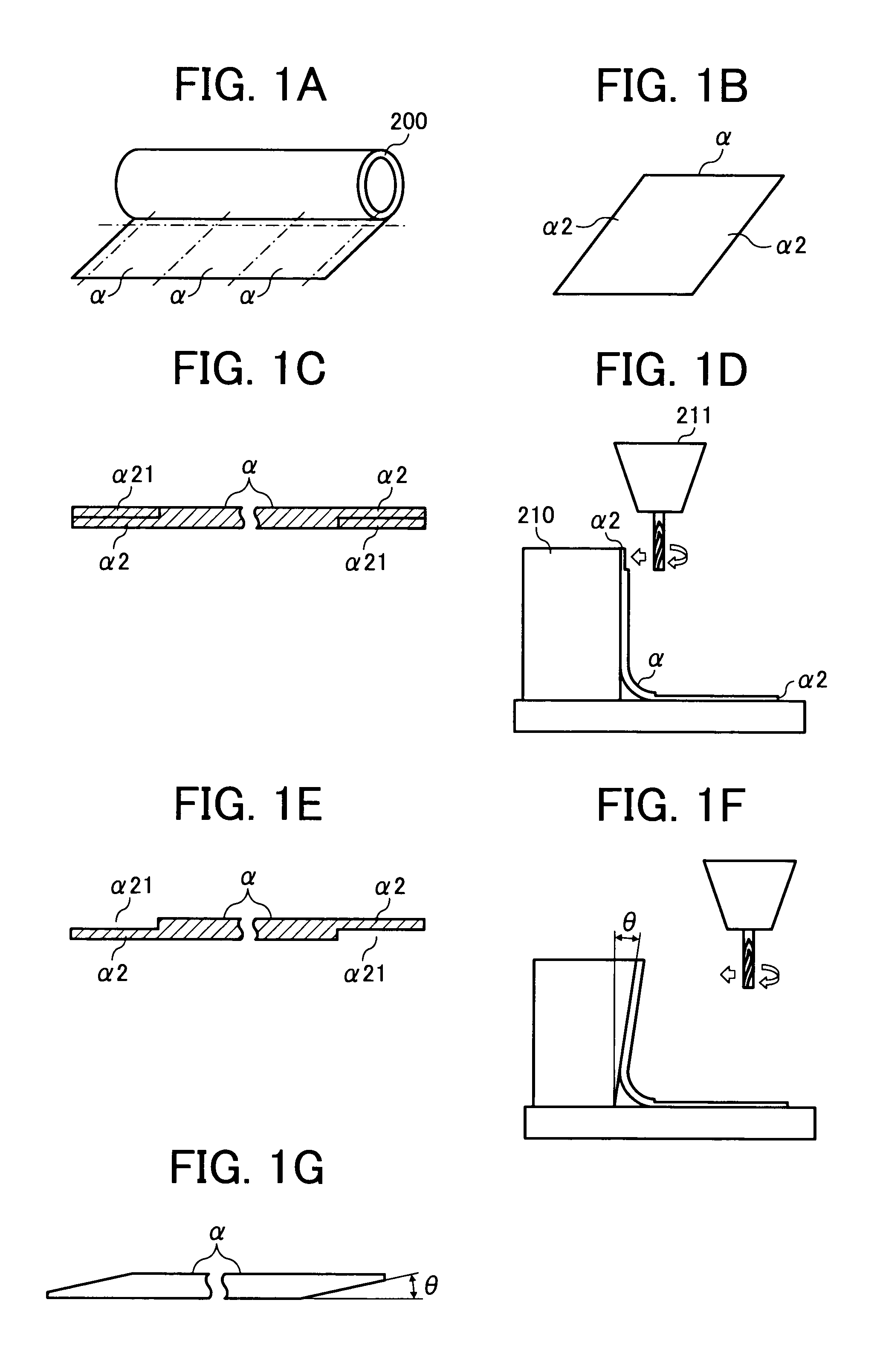
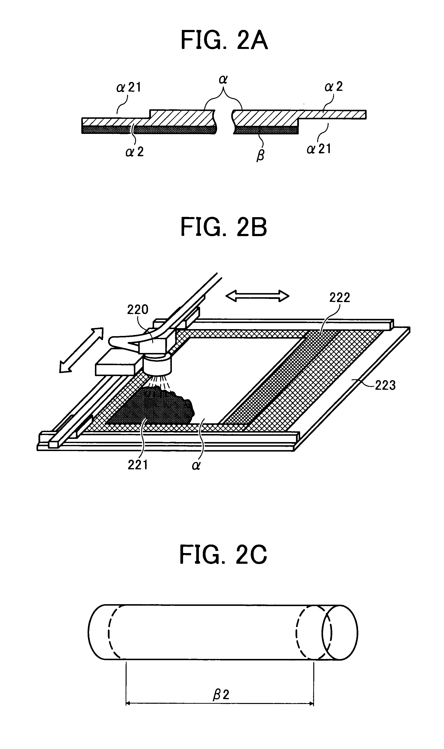
[0066]In order to form finally a cylindrical body as a belt having a length of 320 mm and an external diameter of 60 mm, a polyimide film (Kapton®, 300H, DU PONT-TORAY CO., LTD.) having a thickness of 75 μm was cut so that a sheet was obtained (see FIG. 1B). The thinned portion α21 was formed on each of opposite surfaces of the opposite end portions α2 (a length of 340 mm) of the sheet α to be joined by grinding such that the thickness of the thinned portion α21 was 35 μm in a range of 10 mm from each of opposite ends of the sheet (see FIGS. 1C to 1E).

[0067]A conductive film-material was applied to the sheet as follows. A material having a solid content of a polyimide precursor of 40 weight %, a polyphenylene sulfide of 30 weight %, and a conductive carbon (powder) of 30 weight % was dispersed in water such that it had a...


PUM

PropertyMeasurementUnit
thicknessaaaaaaaaaa
thicknessaaaaaaaaaa
melting temperatureaaaaaaaaaa

Abstract

A base element for a fixing belt are provided. The base element includes a sheet which is made of a heat resistant resin and has opposite end portions joined in an endless state. A conductive film layer of a thickness of 3 to 15 μm is provided over two third or more area of an inner surface of the endless belt.

Description

CROSS REFERENCE TO RELATED APPLICATIONS[0001]This application is based on and claims priority from each of Japanese Patent Application Nos. 2006-203352, filed on Jul. 26, 2006 and 2007-045349, filed on Feb. 26, 2007, the disclosure of which is incorporated herein by reference in its entirety.BACKGROUND OF THE INVENTION[0002]1. Field of the Invention[0003]The present invention relates to a fixing belt used in an image forming apparatus such as an electrophotographic copier, a laser printer, facsimile or the like, a base element for the fixing belt and an image forming apparatus having the fixing belt. The present invention also relates to a method for producing the base element.[0004]2. Description of the Related Art[0005]FIG. 5 illustrates an explanatory view of a conventional image forming apparatus in an electrophotographic system. The conventional image forming apparatus 100 in the electrophotographic system, for example, a copying machine or a laser printer includes a photocondu...

Claims


Application Information

Patent Timeline
Patent Type & Authority Patents(United States)
IPC IPC(8): B29D29/10F16G1/06
CPCB29D29/00G03G15/2057Y10T428/19Y10T428/265Y10T428/192G03G2215/2016
Inventor KATABAMI, HIROSHIMATSUO, MINORUFUKUI, SHIGENOBU
Owner RICOH KK
Why Eureka
Try Eureka