

Method for Making an Object
a three-dimensional, object-making technology, applied in the direction of photomechanical equipment, manufacturing tools, instruments, etc., can solve the problems of compromising the longevity of the equipment, not providing the printing plate of a commercially viable resolution, and increasing the cost of the apparatus, so as to achieve the effect of reducing the purchase cost, reducing the cost, and reducing the cos
- Summary
- Abstract
- Description
- Claims
- Application Information
AI Technical Summary
Benefits of technology
Problems solved by technology
Method used
Image

Examples
example 1
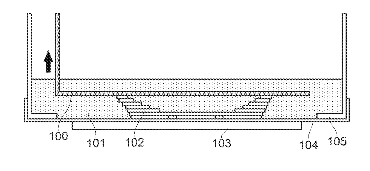
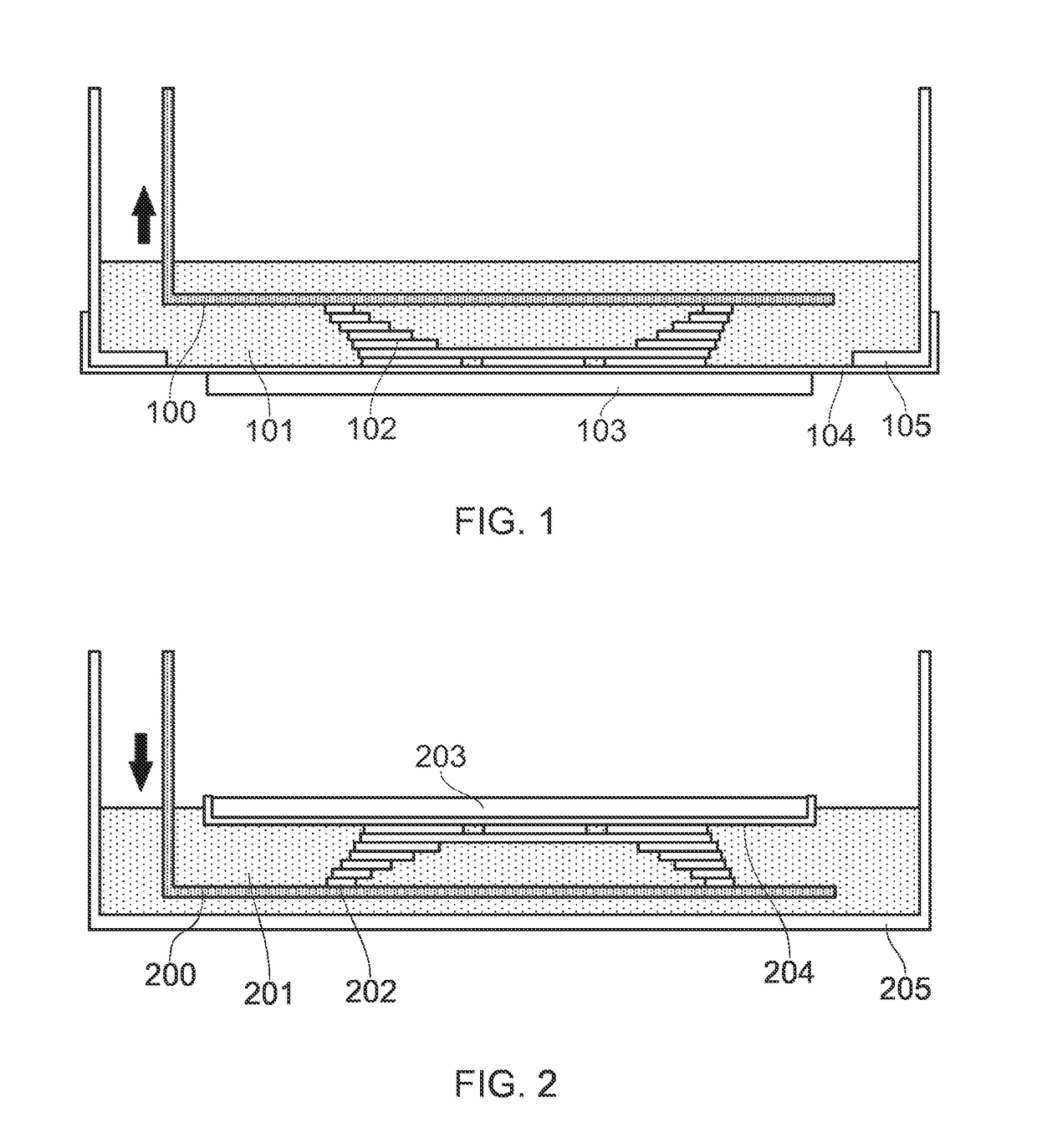
Apparatus and Method
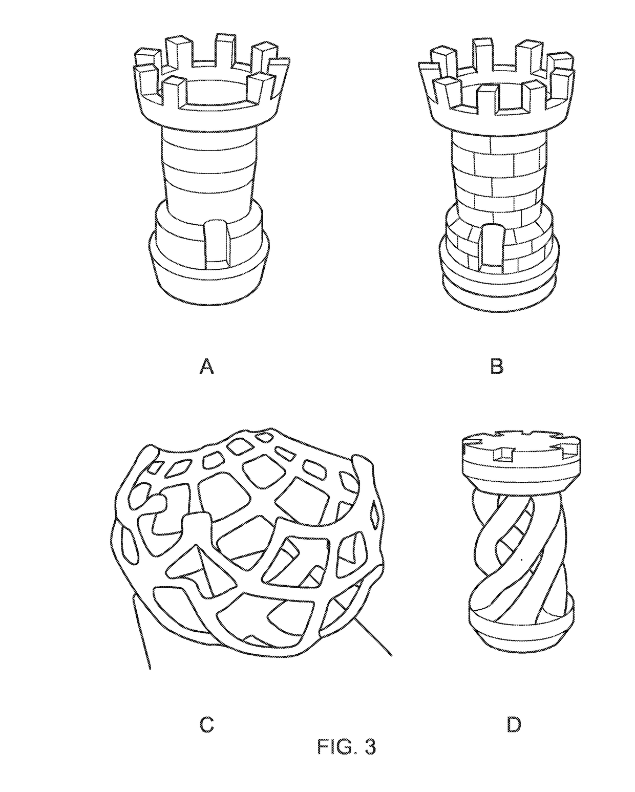
[0077]A 3D printer was constructed in the following manner, a central processing unit was programmed with the driver software and connected to a drive motor that vertically raised or declined a platform by small increments, typically 0.1 mm. The image to be printed was a detailed chess piece which was scanned using 3D scanning software such as reconstructme.net from Profactor and created using Google SketchUp from Google Inc. The resultant computer image file was stored in stereolithography format (STL).
[0078]The image was split into slices that were 0.1 mm thick and these images were sent sequentially to the screen as black and white files. The length of time the image was displayed on the screen, the illuminating time, was a constant for all the image slices after the first layer. This was calculated as the time required for the chosen screen to polymerise 0.1 mm of the liquid polymer.
[0079]A VGA type 4:3 resolution 8″ LCD colour monitor with VGA BNC AV Port, m...
example 2 -
Example 2-Faster formulation
[0089]To investigate the optimised rate of growth of the polymer under LCD illumination with different levels of addition of bis(.eta.5-2,4-cyclopentadien-1-yl)-bis(2,6-difluoro-3-(1H-pyrrol-1-yl)-phenyl) titanium (titanocene made by BASF under the tradename Irgacure 784), 500 g of a standard polymer formulation was made to test it in. A glass vessel was loaded with 325 g of Genomer 4302, an aliphatic polyester triurethane, manufactured by Rahn AG of Switzerland, 130 g of TEDGMA (tri-ethylene dimethacrylate) a reactive diluent manufactured by Sartomer under the trade SR205 to it, 45 g of TMPTMA (trimethylolpropane trimethacrylate) a reactive diluent manufactured by Sartomer under the trade SR350. To this, the following percentages of bis(.eta.5-2,4-cyclopentadien-1-yl)-bis(2,6-difluoro-3-(1H-pyrrol-1-yl)-phenyl) titanium) were separately added, 0.1%, 0.2%, 0.3%, 0.4%, 0.5%, 0.6%, 0.7%, 0.8%, 0.9%, 1.0%, 1.1%, 1.2%, 1.3%, 1.4% and 1.5%. Each composition wa...
example 3
Coated Screen
[0093]500 g of the light polymerisable compound was composed in the following manner. A glass vessel was loaded with 325 g of Genomer 4302, an aliphatic polyester triurethane, manufactured by Rahn AG of Switzerland, 130 g of TEDGMA (tri-ethylene dimethacrylate) a reactive diluent manufactured by Sartomer under the trade SR205 to it, 41.25 g of TMPTMA (trimethylolpropane trimethacrylate) a reactive diluent manufactured by Sartomer under the trade SR350 and 3.75 g of (bis(.eta.5-2,4-cyclopentadien-1-yl)-bis(2,6-difluoro-3-(1H-pyrrol-1-yl)-phenyl) titanium) a photoinitiator manufactured by BASF under the trade name Irgacure 784. They were mixed at 60° C. for a total of 3 hours and allowed to cool.
[0094]The LCD screen was a VGA type 4:3 resolution 8″ LCD colour monitor with VGA BNC AV Port, manufactured by Samsung. It provided a 800 (horizontal)×600 pixel resolution (vertical) with a viewing area of 162 mm wide by 121.5 mm high and a viewing angle of 130 degrees high by 115...
PUM
| Property | Measurement | Unit |
|---|---|---|
| Fraction | aaaaa | aaaaa |
| Fraction | aaaaa | aaaaa |
| Fraction | aaaaa | aaaaa |
Abstract
Description
Claims
Application Information