Electricity and synthesis gas generation method

a technology of synthesis gas and electricity, applied in the direction of electrochemical generators, machines/engines, turbine/propulsion fuel heating, etc., can solve the problems of electricity production costs, and achieve the effects of reducing the fuel requirements of gas turbines, economic efficiencies, and reducing the cost of electricity production

Active Publication Date: 2008-12-23
PRAXAIR TECH INC
View PDF12 Cites 11 Cited by
  • Summary
  • Abstract
  • Description
  • Claims
  • Application Information

AI Technical Summary

Benefits of technology

[0007]By utilizing a fuel that in major part is not derived from the synthesis gas stream and ratios of flow rates of the fuel and the synthesis gas stream of 1.5 and greater, the low temperature heat, which in the prior art is simply dissipated, can be used to preheat fuel to the gas turbine. Such preheating decreases the fuel requirements of the gas turbine and therefore, the cost in producing electricity. Such a reduced cost can be applied to the entire integration of electricity and synthesis gas production, and therefore hydrogen production, to provide economic efficiencies in an integration of the present invention that are not obtained in the prior art.

Problems solved by technology

Such preheating decreases the fuel requirements of the gas turbine and therefore, the cost in producing electricity.

Method used


Image

  • Electricity and synthesis gas generation method
  • Electricity and synthesis gas generation method
  • Electricity and synthesis gas generation method

Examples


example 1

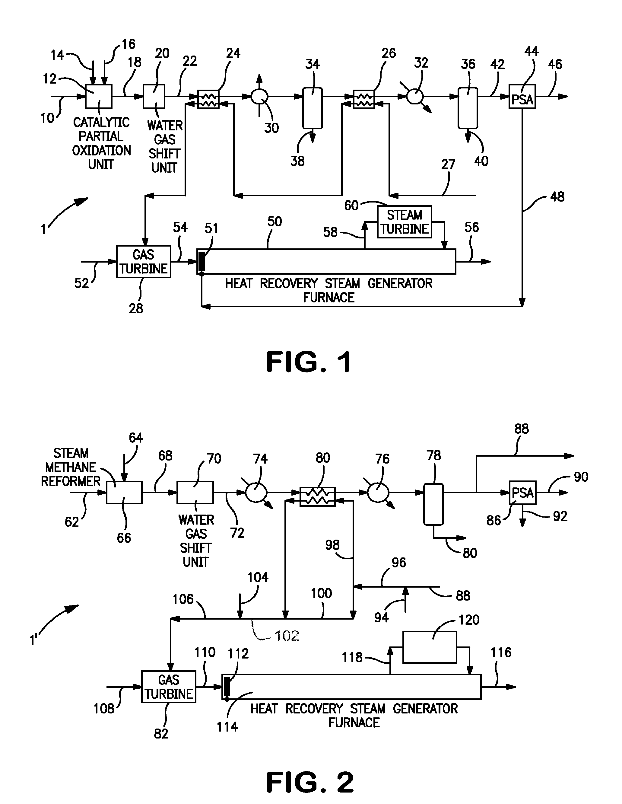
[0034]For purposes of this example, synthesis gas stream 72 has a flow rate of about 860 lb-mol / hr and has the following composition: 48 mol percent hydrogen, 35.7 mol percent water, 1.9 mol percent carbon monoxide, 10.8 mol percent carbon dioxide, 0.6 mol percent nitrogen and 3.0 mol percent methane. After passage through heat exchanger 74, synthesis gas stream 72 has a pressure of about 238 psia and a temperature of about 372° F. Assuming a hydrogen recovery of about 83 percent, approximately 3.12 MMSCFD hydrogen would be produced for hydrogen product stream 90. In heat exchanger 80, the synthesis gas stream 72 is further cooled to 100° F. against subsidiary stream 98 that constitutes about 62 percent of combined stream 96. Subsidiary stream 98 emerges from heat exchanger 80 at a temperature of about 322° F., which upon mixing with subsidiary stream 100, produces fuel stream 106 at a temperature of about 227° F. In this example no additional fuel is used and hence, subsidiary fuel...

example 2

[0035]This example is a modification of Example 1 in which synthesis gas stream 72 has a flow rate of about 1385 lb-mol / hr and the same composition and temperature and pressure after having been cooled in heat exchanger 74. Again, assuming a recovery of hydrogen of about 83 percent, about 5.02 MMSCFD hydrogen would be produced for hydrogen product stream 90. Furthermore, in this example it is assumed that all of fuel stream 84 passes through heat exchanger 80 to cool synthesis gas stream 72 to about 100° F. The resultant fuel stream 106 has a temperature of about 322° F., which decreases fuel consumption by about 0.76 percent.

example 3

[0036]This example is similar to that of Example 2, but with synthesis gas stream 72 having a different composition than that previously considered due to additional process heat recovery within water gas shift unit 70. In this regard, for purposes of this example, synthesis gas stream 72 is assumed to have the following composition: 63.9 mol percent hydrogen, 13.2 mol percent water, 2.8 mol percent carbon monoxide, 14.1 mol percent carbon dioxide, 0.7 mol percent nitrogen and 5.3 mol percent methane. As a result of the additional process heat recovery, synthesis gas stream 72 has a lower stream temperature after heat exchanger 74, namely 277° F. as opposed to 372° F. in the previous examples and consequently a lower moisture content due to condensation removed in an upstream knock-out drum that as would be known in the art could be associated with water gas shift unit 70. Further, in this example, synthesis gas stream 72 must only be cooled from about 277° F. to about 110° F. As su...


PUM


Abstract

A method of generating electricity in synthesis gas in which a fuel is combusted in a gas turbine to generate the electricity that at least about 60 percent by volume is derived from a source independent of the synthesis gas. The synthesis gas is produced by reacting a hydrocarbon stream, by for example, partial oxidation, autothermal reforming or steam methane reforming. After the synthesis gas stream is cooled, heat is transferred from the heated synthesis gas stream to the fuel prior to combustion in the gas turbine. All or at least a portion of the heat is transferred at a temperature no greater than about 500° F. and at a flow ratio of the fuel to the gas turbine to the synthesis gas stream from at least about 1.5. The heating of the fuel to the gas turbine lowers fuel consumption and thereby the total expenses involved in generating electricity and syngas.

Description

FIELD OF THE INVENTION[0001]The present invention provides a method of generating electricity and synthesis gas in which heat is transferred from a synthesis gas stream to a fuel fed to combustors of a gas turbine used in generating the electricity. More particularly, the present invention relates to such a method in which the heat is transferred at a low temperature of no greater than about 500° F. and the fuel fed to the gas turbine has a composition that is at least 60 percent volume derived from a source that is independent of the synthesis gas stream.BACKGROUND OF THE INVENTION[0002]Synthesis gases, that is, gases that contain hydrogen and carbon monoxide are produced by steam methane reforming, autothermal reforming, partial oxidation, either catalytic or non-catalytic. The resultant synthesis gas stream can be further processed in a water gas shift reactor to increase its hydrogen content and the hydrogen can be separated from the synthesis gas to produce a hydrogen product s...

Claims


Application Information

Patent Timeline
Patent Type & Authority Patents(United States)
IPC IPC(8): F02C3/28F02C6/18F02C7/224
CPCC01B3/386F01K23/067F02C3/22F02C7/224C01B2203/0233C01B2203/0244C01B2203/0261C01B2203/0283C01B2203/043C01B2203/047C01B2203/0475C01B2203/06C01B2203/1241C01B2203/84H01M8/0606Y02E20/18Y02E20/16Y02E60/50
Inventor RAYBOLD, TROY MICHAELDRNEVICH, RAYMOND FRANCISMEAGHER, JAMES PATRICK
Owner PRAXAIR TECH INC
Why Eureka
Try Eureka