
Dynamic fan speed control for aerodynamic drag reduction

a technology of aerodynamic drag reduction and fan speed control, which is applied in the direction of electric propulsion mounting, machines/engines, transportation and packaging, etc., can solve the problems of increasing the cost of construction or implementation, increasing the cost of construction, and continuing to suffer from a number of limitations and shortcomings, so as to reduce the aerodynamic drag of a vehicle, reduce the overall fuel demand, and improve the fuel efficiency of operation of the vehicle

Active Publication Date: 2020-05-12
CUMMINS INC
View PDF10 Cites 0 Cited by
  • Summary
  • Abstract
  • Description
  • Claims
  • Application Information

AI Technical Summary

Benefits of technology

The system effectively reduces aerodynamic drag and fuel consumption by selecting an optimal fan speed, resulting in improved fuel efficiency without the need for additional components or changes to vehicle configuration, maintaining simplicity and cost-effectiveness.

Problems solved by technology

However, such developments continue to suffer from a number of limitations and shortcomings, including complexity in operation or design, costly construction or implementation, and lack of interchangeability among different vehicle configurations.

Method used


Image

  • Dynamic fan speed control for aerodynamic drag reduction
  • Dynamic fan speed control for aerodynamic drag reduction
  • Dynamic fan speed control for aerodynamic drag reduction

Examples


Embodiment Construction

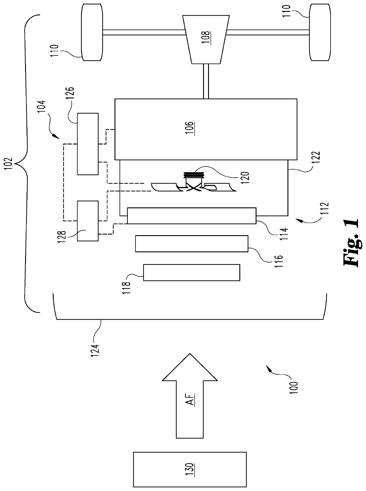
[0003]For the purposes of clearly, concisely and exactly describing illustrative embodiments of the present disclosure, the manner and process of making and using the same, and to enable the practice, making and use of the same, reference will now be made to certain exemplary embodiments, including those illustrated in the figures, and specific language will be used to describe the same. It shall nevertheless be understood that no limitation of the scope of the invention is thereby created, and that the invention includes and protects such alterations, modifications, and further applications of the exemplary embodiments as would occur to one skilled in the art.

SUMMARY OF THE DISCLOSURE

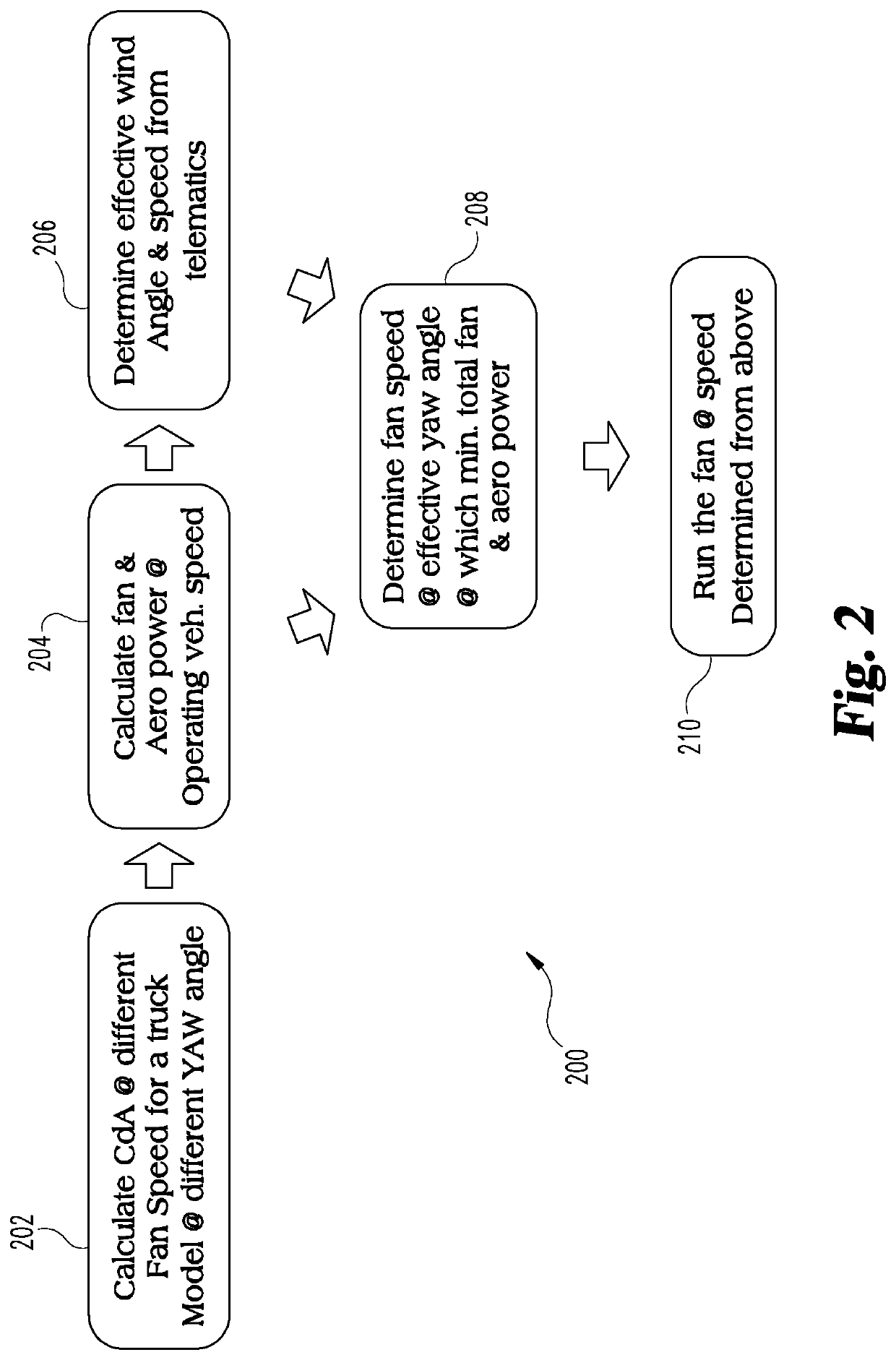
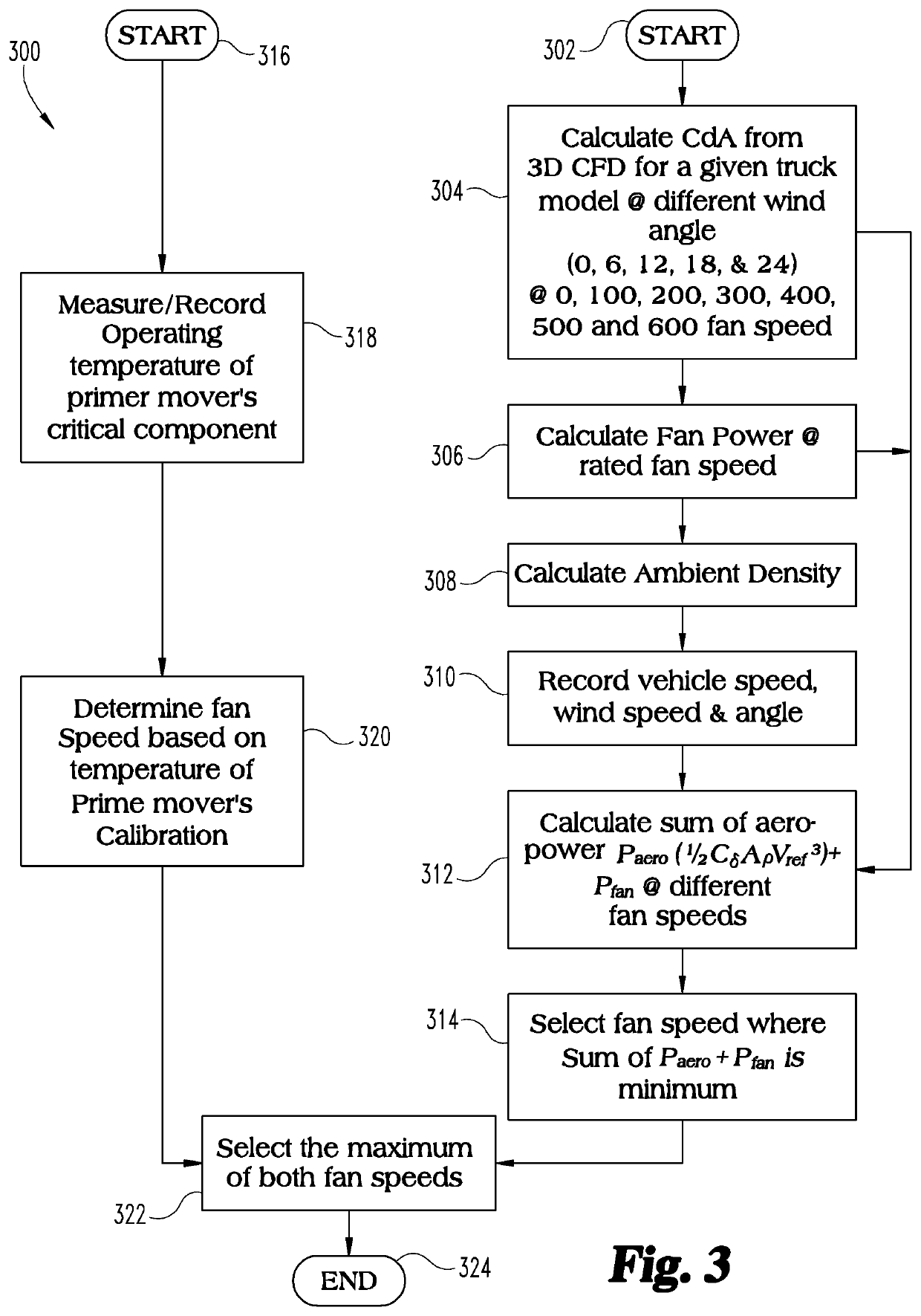
[0004]Embodiments disclosed herein include a unique system, method, and apparatus that optimizes control of the rotational speed of a fan in a vehicle in a manner that is effective to reduce the aerodynamic drag of a vehicle, and accordingly to improve fuel efficiency of operation of the vehicle. Certa...


PUM


Abstract

A method, system, and apparatus are provided for optimizing control of the rotational speed of a fan in a vehicle so as to reduce the aerodynamic drag of a vehicle in a given operating parameter, and accordingly, to improve fuel efficiency of operation of the vehicle. Certain exemplary embodiments include determining an optimized speed of rotation of a cooling fan of the vehicle for reducing overall fuel demand in given operating conditions, and controlling rotation speed of the fan at the optimized speed in order to minimize fueling demand of a prime mover of the vehicle.

Description

CROSS-REFERENCE TO RELATED APPLICATION[0001]This application claims the benefit of the filing date of U.S. Provisional Application Ser. No. 62 / 585,666 filed on Nov. 14, 2017, which is incorporated herein by reference in its entirety.BACKGROUND[0002]The present application generally relates to dynamic control of cooling fan speed in a vehicle equipped with a prime mover, providing a method, an apparatus, and a system for reducing aerodynamic drag of vehicles by optimizing fan speed. A number of methods, systems, and apparatus have been developed for reducing the aerodynamic drag of vehicles in order to improve their fuel efficiency. However, such developments continue to suffer from a number of limitations and shortcomings, including complexity in operation or design, costly construction or implementation, and lack of interchangeability among different vehicle configurations. Therefore, a significant need remains for further improvements in systems, apparatus, and methods for reducin...

Claims


Application Information

Patent Timeline
Patent Type & Authority Patents(United States)
IPC IPC(8): B60K11/00B60H1/00B60K11/06F01P7/04
CPCF01P7/042B60H1/00821B60K11/06B60H1/00878F01P7/048B60H1/00764F01P7/04F01P2050/22B60K2001/006
Inventor SAHA, ROHITHWANG, LONG K.
Owner CUMMINS INC
Learn More