Rolling bearing and rolling bearing assembly

a technology of rolling bearings and assemblies, which is applied in the direction of rolling contact bearings, rotary bearings, shafts and bearings, etc., can solve the problems of aforesaid problems, waste of lubricant, and seizure, so as to prevent seizure in cages, reduce the amount of lubricant, and reduce the effect of lubricant consumption

Active Publication Date: 2012-05-08
JTEKT CORP
View PDF16 Cites 9 Cited by
  • Summary
  • Abstract
  • Description
  • Claims
  • Application Information

AI Technical Summary

Benefits of technology

[0007]The invention has been made in view of these situations, and an object thereof is to provide a rolling bearing and a rolling bearing assembly which can prevent the occurrence of seizure in the cage even though only a small amount of lubricant is used and therefore can prevent the wasteful usage of lubricant.

Problems solved by technology

In an angular contact ball bearing described in JP-A-2004-347001, in the event that the amount of lubricant that is applied in advance is small, a lubrication failure is produced at a sliding contact portion between a shoulder portion of an outer ring and an outer circumferential surface of a cage to thereby cause a problem that seizure occurs in the cage, whereas in the event the amount of lubricant so applied is more than required, extra lubricant flows out of the rolling bearing to thereby cause a problem that the lubricant is used wastefully.
In addition, in a rolling bearing assembly disclosed in JP-A-2004-108388, there has been a fear that the aforesaid problems would occur in the event that such an outer ring guiding type angular contact ball bearing is used as a rolling bearing that is used therein.

Method used


Image

  • Rolling bearing and rolling bearing assembly
  • Rolling bearing and rolling bearing assembly
  • Rolling bearing and rolling bearing assembly

Examples


example 1

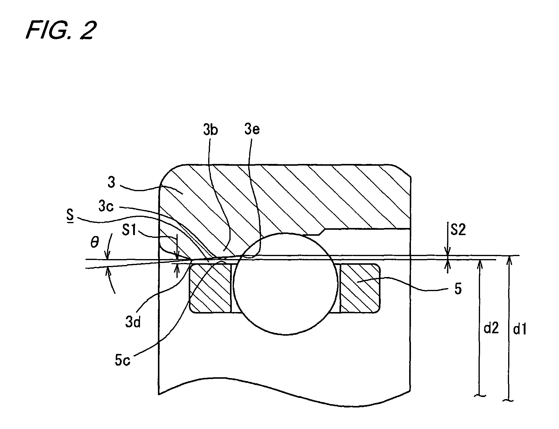
[0057]An angular contact ball bearing shown in FIG. 6 was prepared as a sample bearing 21 having an inside diameter (D1) of 70 mm, an outside diameter (D2) of 110 mm, and an assembled width (W) of 20 mm. This sample bearing 21 is such that a cage 25 is guided by a shoulder portion 23b on one side of an outer ring 23. A guiding surface 23c of the shoulder portion 23b is made into a tapered surface, and a difference S2 between an inside diameter (95.212 mm) of a rolling element side end portion 23e and an inside diameter (95.2 mm) of an external end portion 23d of the guiding surface 23c is 0.012 mm. In addition, an angle θ of the guiding surface 23c of the outer ring 23 is 0.17°.

[0058]The sample bearing 21 was washed and degreased, and a total of 20 μL of spindle oil (VG 22), 10 μL to balls 24 and 10 μL to a guided surface 25b of the cage 25 and the guiding surface 23c of the outer ring 23, was applied to those constituent parts using a micro syringe from the outside as initial lubri...

example 2

[0063]The sample bearing 21 was tested in the similar way in which the sample bearing 21 of Example 1 was tested. However, in Example 2, the sample bearing 21 was rotated without cooling the jacket. The results of the tests carried out are shown in Table 1.


PUM


Abstract

There is provided a rolling bearing including an inner ring having an inner ring raceway surface, an outer ring having an outer ring raceway surface and a shoulder portion formed on one axial side of the outer ring raceway surface, a plurality of rolling elements which roll between the inner ring raceway surface and the outer ring raceway surface, and a cage adapted to hold the plurality of rolling elements at predetermined intervals in a circumferential direction and having a guided surface which confronts the shoulder portion of the outer ring in such a manner as to be brought into sliding contact therewith. The rotation of the cage is guided through sliding contact of the guided surface of the cage with a guiding surface of the shoulder portion of the outer ring. A guiding space which is a radial space between the guiding surface of the shoulder portion of the outer ring and the guided surface of the cage is made to increase as approaching the rolling elements.

Description

BACKGROUND OF THE INVENTION[0001]1. Filed of the Invention[0002]The present invention relates to a rolling bearing and a rolling bearing assembly which is lubricated by a lubricant supplied from an oil filling device.[0003]2. Related Art[0004]Conventionally, as angular contact ball bearings which have an inner ring, an outer ring, balls as rolling elements which are disposed between those rings, and a cage for retaining the balls, so-called outer ring guiding type rolling bearings have been proposed in which the rotation of the cage is guided through sliding contact of one shoulder portion of the outer ring and an outer circumference of the cage (refer to JP-A-2004-347001).[0005]On the other hand, there have been proposed rolling bearing assemblies which include an oil filling unit having a pump for discharging a lubricant into an interior of a rolling bearing and a tank for containing the lubricant oil for filling a required amount of lubricant as required, whereby the lubricant oi...

Claims


Application Information

Patent Timeline
Patent Type & Authority Patents(United States)
IPC IPC(8): F16C33/38F16C33/66
CPCF16C19/163F16C33/3806F16C33/6674F16C33/664F16C33/3856F16C2300/02
Inventor SUZUKI, KAZUYATANI, NAOKIMURATA, JUNJIYAMAKAWA, KAZUYOSHI
Owner JTEKT CORP
Why Eureka
Try Eureka