Wet-type exhaust desulfurizing apparatus

a technology of exhaust gas and desulfurizing equipment, which is applied in the direction of fuel gas production, dispersed particle separation, separation processes, etc., can solve the problems of affecting the overall desulfurization performance, affecting the absorption performance of exhaust gas sox at portions, and preventing adequate gas-liquid contact, so as to reduce the required circulation amount, improve contact efficiency, and reduce the effect of a required amoun

Active Publication Date: 2012-05-08
MITSUBISHI POWER LTD
View PDF7 Cites 2 Cited by
  • Summary
  • Abstract
  • Description
  • Claims
  • Application Information

AI Technical Summary

Benefits of technology

[0029]According to the first aspect of the present invention, by cooperation of the trough installed at the upper portion of the gas entrance (duct) of the absorbing tower and the nose of horseshoe shape at the portion excepting the gas entrance, the gas-liquid contact efficiency is improved over the conventional art, the exhaust gas desulfurization performance is also improved in comparison to the conventional art, reduction of a required circulation amount of the absorbing liquid, and reduction of power of a circulating pump can be achieved. Also, by combination of the trough disposed at the gas entrance of the absorbing tower and the horseshoe-shaped nose disposed at the inner wall surface at the portion excepting the gas entrance, the pressure loss at the gas entrance of the absorbing tower can be reduced in comparison to the conventional art and reduction of power of a desulfurizing fan is enabled.
[0030]According to the second aspect of the present invention, in addition to providing the effects of the first aspect of the present invention, by making a size of an opening of the gas entrance be of a range spreading at an angle of 90° or more in the horizontal direction and centered about the hypothetical vertical axis line of the tower center portion with respect to the absorbing tower, drift at the entrance can be prevented, and also, by setting an upper limit of the size of the opening of the entrance to 180° centered about the hypothetical vertical axis line of the tower center portion, the strength of the absorbing tower can be maintained.
[0031]According to the third aspect of the present invention, in addition to providing the effects of the first or second aspect of the present invention, by setting the protrusion length of the nose in a range of 100 to 500 mm, the liquid that flows down along the tower wall can be rescattered satisfactorily, the blow-by of gas can be lessened as much as possible, and the pressure loss of the ascending flow of the gas inside the tower can be suppressed (see FIG. 4).
[0032]According to the fourth aspect of the present invention, in addition to providing the effects of any of the first to third aspects of the present invention, by installing the nose at the position below the spray header of the lowermost stage (first stage) at which the amount of the absorbing liquid flowing down along the wall surface is the highest, a high effect of causing the absorbing liquid, flowing as a liquid film that flows down along the wall surface of the absorbing tower, to be rescattered into the absorbing tower is provided.
[0033]According to the fifth aspect of the present invention, in addition to providing the effects of any of the first to third aspects of the present invention, by installing the nose at the position between the spray headers of the lowermost stage and the stage adjacently above the lowermost stage at which the amount of the liquid flowing down along the wall surface is the second highest, a high effect of causing a portion of the sprayed absorbing liquid, flowing as a liquid film that flows down along the wall surface of the absorbing tower, to be rescattered into the absorbing tower is provided, and by positioning the nose at the tower side wall surface opposite the gas entrance of the absorbing tower, the pressure loss with respect to the ascending flow of gas is lowered in degree.
[0034]According to the sixth aspect of the present invention, in addition to providing the effects of any of the first to fifth aspects of the present invention, by configuring the nose as noses disposed on the tower side wall in a manner that is stepped in the vertical direction so as not to overlap mutually in the vertical direction, the absorbing liquid that is rescattered by each nose is prevented from becoming a uniform liquid film in a horizontal section inside the absorbing tower and an increase in the pressure loss can thus be prevented.

Problems solved by technology

When there is such a bias in spray droplet density of the absorbing liquid inside the absorbing tower 4, a large amount of the exhaust gas flows to a portion of low droplet density, preventing adequate gas-liquid contact, degrading exhaust gas SOx absorption performance at portions, and thus affecting the overall desulfurization performance.

Method used


Image

  • Wet-type exhaust desulfurizing apparatus
  • Wet-type exhaust desulfurizing apparatus
  • Wet-type exhaust desulfurizing apparatus

Examples


Embodiment Construction

[0044]Embodiments of the present invention shall now be described along with the drawings.

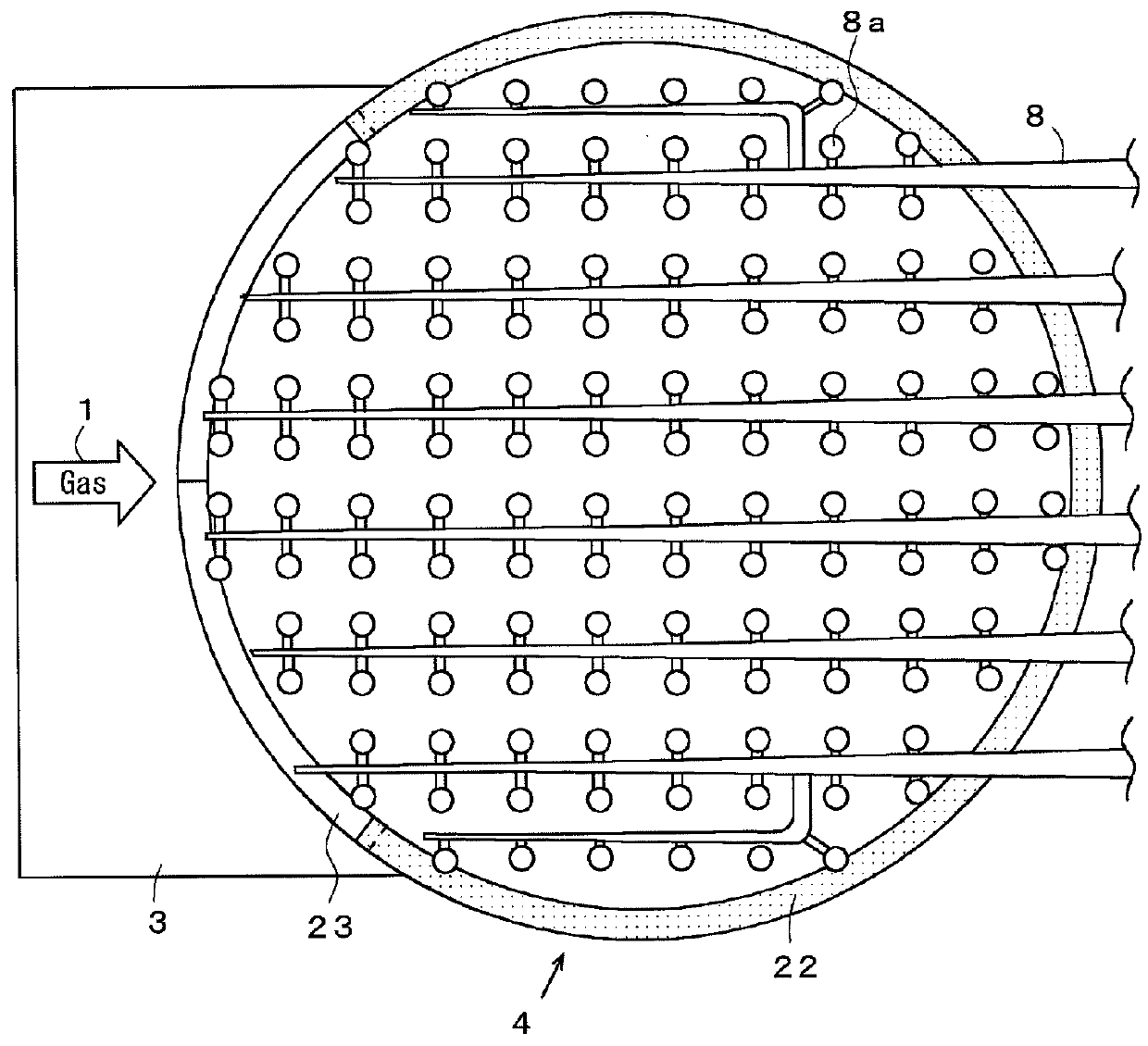
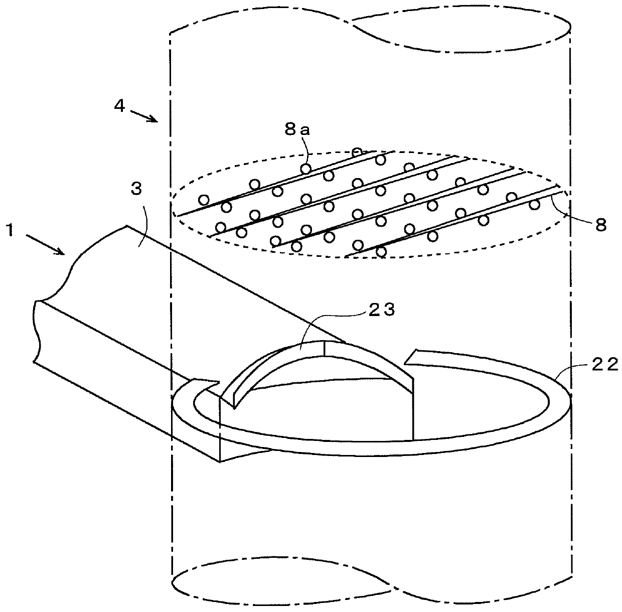
[0045]FIG. 1 is a diagram of an interior of an absorbing tower of a wet-type exhaust desulfurizing apparatus according to the embodiment as viewed from a horizontal section direction, and FIG. 2 is a partial perspective view of the interior of the absorbing tower of FIG. 1. Along an outer circumference excepting an exhaust gas entrance 3 of a tower wall portion of the absorbing tower 4, a horseshoe-shaped nose 22 is protruded into the tower in a horizontal direction, and a trough 23 is installed at an upper portion of a region of the absorbing tower exhaust gas entrance (duct) 3 in which the horseshoe-shaped nose 22 is not disposed.

[0046]To prevent drift at the entrance 3, a size of an opening of the gas entrance (duct) 3 is set to be of range spreading at an angle of 90° or more in the horizontal direction and centered about a hypothetical vertical axis line of a tower center portion with resp...


PUM

PropertyMeasurementUnit
spraying angleaaaaaaaaaa
angleaaaaaaaaaa
lengthaaaaaaaaaa

Abstract

An absorbing tower is provided in its side wall with a gas entrance for introducing a combustion exhaust gas into the absorbing tower, and an absorbing liquid is sprayed from the nozzles of a spray header into the exhaust gas introduced to rise from the gas entrance. A trough is arranged in the side wall of the absorbing tower and above the gas entrance, and a nose having a horseshoe shape in a top plan view and extending into tower is disposed in the tower side wall portion of the gas entrance other than the portion arranging the trough and at the same or at substantially the same height as the portion of the trough. The absorbing liquid, which is sprayed from the nozzle and drops along the absorbing tower wall portion, is rescattered to the center portion of the absorbing tower excepting the entrance of the absorbing tower, so that the gas-liquid contact efficiency is improved while suppressing an increase in pressure loss, thereby to prevent the drift of the gas at the tower wall portion.

Description

TECHNICAL FIELD[0001]The present invention relates to an exhaust desulfurizing apparatus for purifying fuel combustion exhaust gas emitted from a boiler or other combustion apparatus and particularly relates to a wet-type exhaust desulfurizing apparatus that lessens sulfur oxides (hereinafter referred to as “SOx”), soot dust, fuel components, and fuel substances in the exhaust gas.BACKGROUND ART[0002]As an apparatus for removing sulfur oxides from combustion exhaust gas to prevent air pollution, a wet-type limestone-gypsum desulfurizing apparatus is being put to practical use widely. A system of this desulfurizing apparatus is shown in FIG. 9. An exhaust gas 1 from a boiler, etc., is introduced from a gas entrance 3 into an absorbing tower 4, and by the exhaust gas 1 coming into contact with droplets of an absorbing liquid sprayed from a plurality of spray nozzles 8a disposed in each of spray headers 8 installed in multiple stages in a gas flowing direction inside the absorbing towe...

Claims


Application Information

Patent Timeline
Patent Type & Authority Patents(United States)
IPC IPC(8): B01D47/06
CPCB01D53/185B01D53/504B01D2251/404B01D2251/608B01D2257/2045B01D2257/2047
Inventor UEDA, TAKURONAKAMOTO, TAKANORIKATAGAWA, ATSUSHIOKURA, HAJIMEISHIZAKA, HIROSHI
Owner MITSUBISHI POWER LTD
Why Eureka
Try Eureka