Hydrocarbon transfer system with horizontal displacement

a technology of hydrocarbon transfer system and horizontal displacement, which is applied in the direction of passenger handling apparatus, liquid handling, packaging goods type, etc., can solve the problems of affecting the vessel is submerged below water level, and the access of the deck is not easy to reach, so as to achieve the effect of small volume of space, low stress, and large available deck area

Inactive Publication Date: 2012-05-15
SINGLE BUOY MOORINGS INC
View PDF10 Cites 15 Cited by
  • Summary
  • Abstract
  • Description
  • Claims
  • Application Information

AI Technical Summary

Benefits of technology

[0008]The present invention has as an object to provide a hydrocarbon transfer system in which the above mentioned problems are solved. It is in particular an object of the present invention to provide a hydrocarbon transfer system which leaves a relatively large available deck area and in which the fluid transfer lines take up a relatively small volume of space. It is also an object of the present invention to provide a hydrocarbon transfer system in which the motions imparted to the transfer system can be taken up by a relatively rigid construction. The transfer system should compensate for large draft variations during the offloading of LNG from one structure to the other and be able to bridge varying distances between the moored structures while allowing wave-induced motions which result in relative low stress on the mooring arms. It is again an object to provide a transfer system that bridges a large distance between two structures and which can be adjusted to the different positions of the connection point or connection flanges on the second structure.
[0013]a second end of the transverse duct is attached to an inboard fluid transfer duct on the first structure situated closer to deck level than the transverse duct, via a length-adjustment fluid transfer member which is can be horizontally displaced upon movement of the second end of the transverse duct relative to the inboard fluid transfer duct. By using rigid piping for the transverse fluid transfer duct, a compact construction is achieved which is not subject to large swinging motions induced by wind and waves. The horizontal displacement of the transverse duct of the invention is compensated for by the length-adjustment fluid transfer duct that is situated for its larger part inboard of the vessel in the region of the support structure, such that the deck space occupied is relatively small. A flexible cryogenic hose may be used as a length-adjustment member.
[0015]Hereby the fluid transfer duct can be correctly positioned for each second structure individually. In the desired position the frame will be locked, so that further movement will not be possible. Its is also possible that the moored second structure can move from and toward the first structure and that this movement is compensated by the moveable frame part without creating additional displacements of the connecting member relative to the first structure.
[0017]In a further embodiment of the invention, the first structure comprises a frame part that is displaceable in the height direction as well. An advantage of this embodiment is that the position of the transfer ducts can be adjusted in accordance with the draft variations during offloading or loading LNG from one structure to the other, so to ensure at all times the same motion envelope for the connector end of the transfer duct. Draft variations of the moored second structure in the height direction can be compensated for without creating any additional displacements of the connecting member relative to the first structure. A further advantage is that this allows to first position the connecting member of the hydrocarbon transfer system exactly above the cooperating connecting member of the second vessel and to then lower the connection member of the transfer system in a straight line on the connection member of second structure.

Problems solved by technology

The known transfer system has as a disadvantage that the storage vessel is submerged below water level and that the deck is not accessible.
Furthermore, the flexible fluid transfer duct extends across a relatively large distance and occupies the space between the far side of the storage vessel and the receiving vessel, hence hampering deck access even in case the deck level would be raised above water level.
The curved flexible transfer duct is furthermore subject to uncontrolled swinging motions caused by wind and by wave movements which may result in undesired forces on the points where the flexible duct is connected to the tower and to the structural connector at the end of the vertical suspension member.
The known hydrocarbon transfer system has as a disadvantage that when the connecting member is connected to the second vessel, stress is created in the fluid transfer duct and / or the frame because of movement of the moored second vessel relative to the first vessel.
The combination of large distance, large dimensions of the transfer system and motion envelope creates inertia related fatigue problems within the transfer system.
Stress in the fluid transfer duct and / or the frame can create leakage of the transferred materials.
A further disadvantage of the known hydrocarbon transfer system is that because of the pivoting movement of the vertical transfer duct around the axis extending in the length direction, large displacements of the moored second structure from and towards the first structure can not be compensated.
Another disadvantage of the known hydrocarbon transfer system is that it cannot function correctly over such a large distance if there is a variation in the position of the connection points or flanges on the second structure, as the motion envelope of the end of the transfer duct will be completely different.
Another disadvantage related to the large distance between the two structures and the large variations in draft (up to 5 m) between the two structures during offloading of LNG is that the known loading arms can not provide the same motion envelope of the connector at the end of the fluid duct which is needed in all circumstances.

Method used


Image

  • Hydrocarbon transfer system with horizontal displacement
  • Hydrocarbon transfer system with horizontal displacement
  • Hydrocarbon transfer system with horizontal displacement

Examples


Embodiment Construction

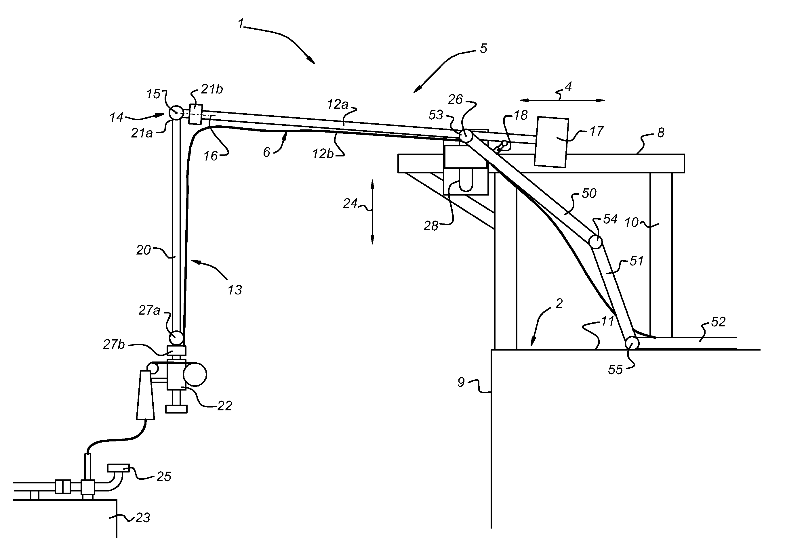
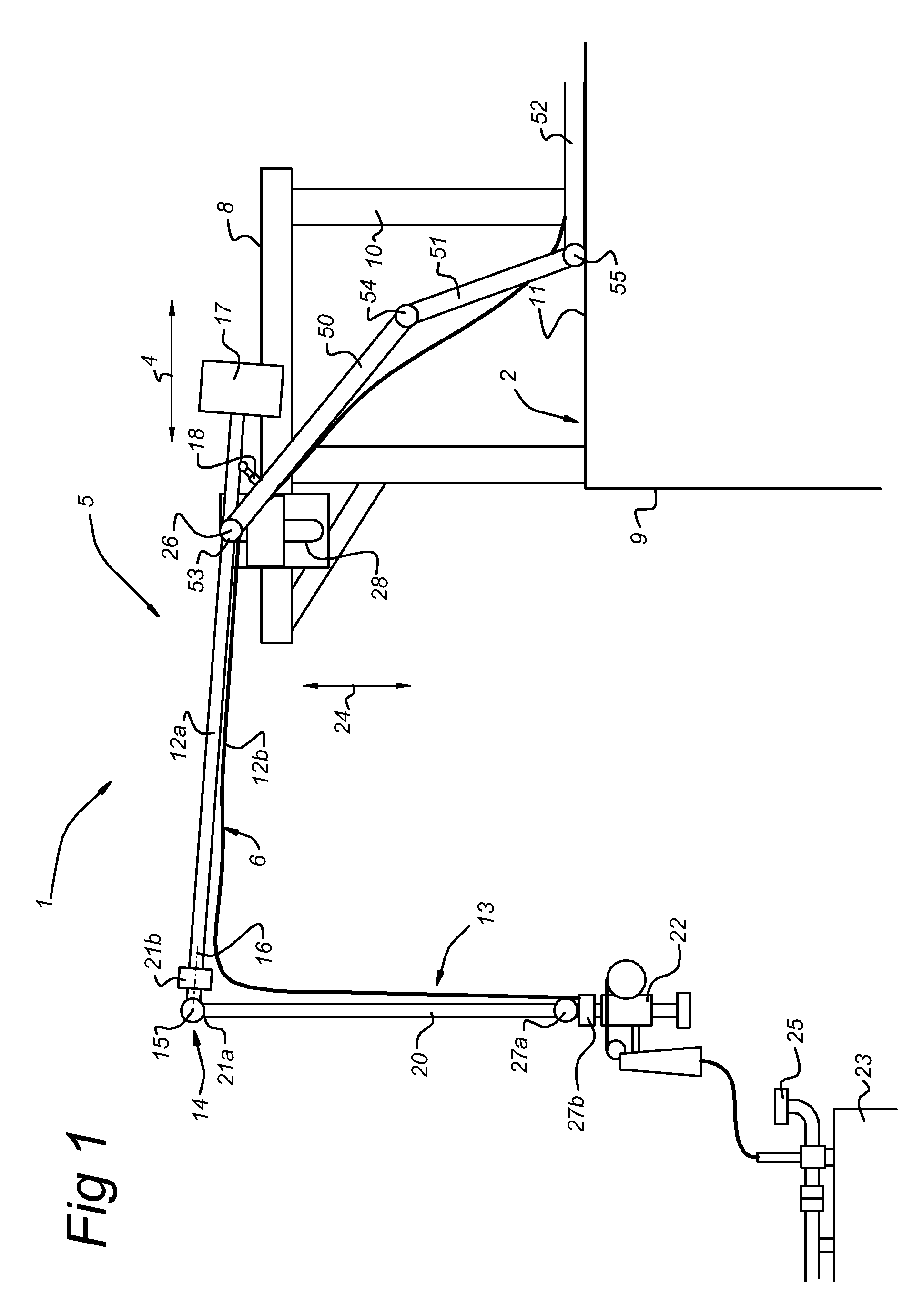
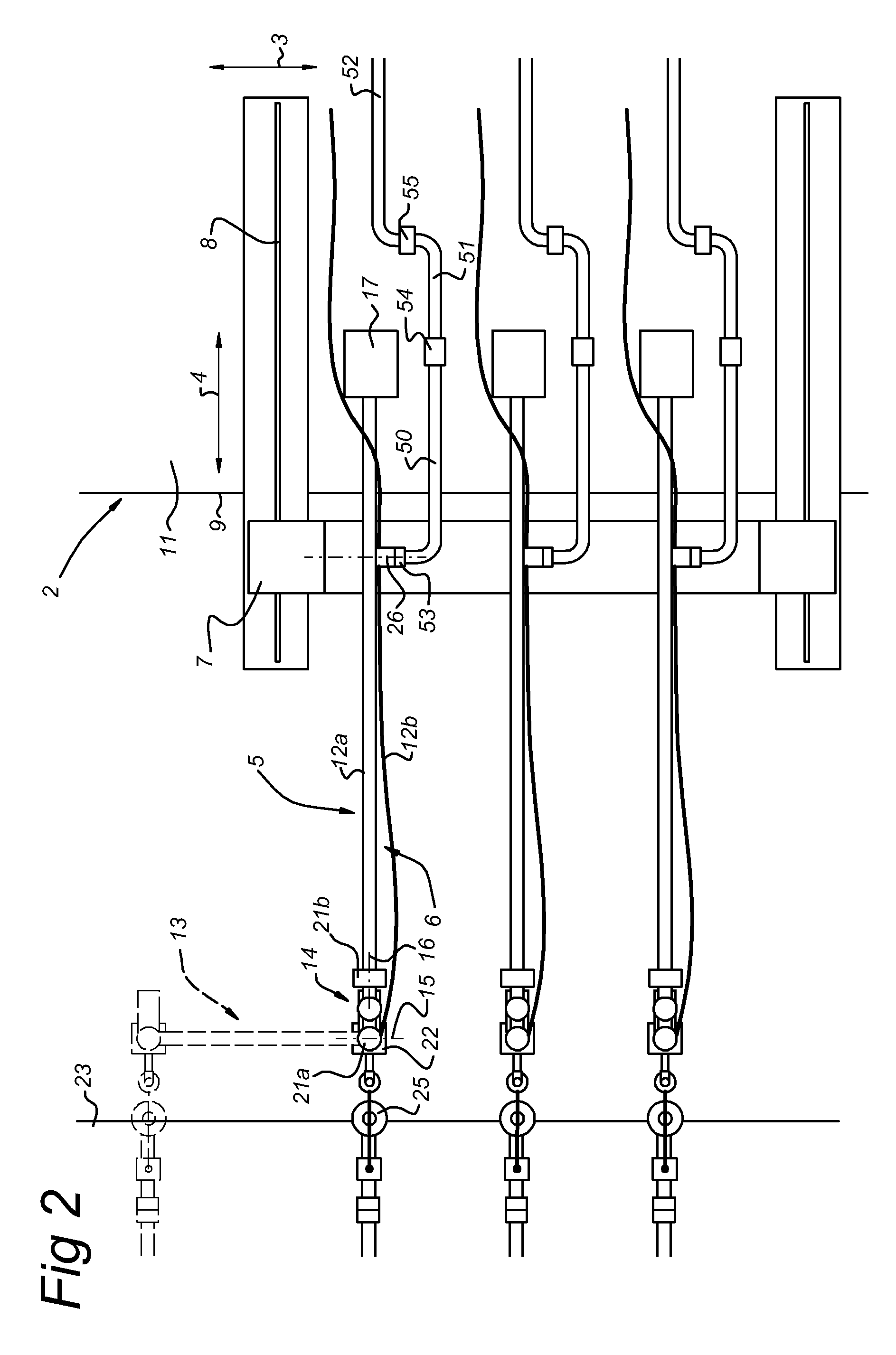
[0026]FIG. 1 shows an embodiment of the hydrocarbon transfer system 1 according the invention. The hydrocarbon transfer system 1 comprises a first structure 2 with a length direction extending perpendicular to the plane of the drawing arrow (3 of FIG. 2), transverse direction 4 and height direction 24. The first structure 2 can be a sea-bed supported gravity based structure (GBS), quay, tower or a floating structure like a spread moored or weathervaning FSRU, a gas liquefaction plant or a floating power plant. The first structure 2 has a frame 5 which carries a fluid transfer duct 20,12a. At its free end the fluid transfer duct has a connecting member 22 for connecting to a cooperating connecting member 25 of a second structure 23. The second structure 23 is moored alongside the first structure 2 and can be a shuttle tanker for transporting LNG. The frame 5 has a movable frame part 7 which is displaceable in the transverse direction 4. The frame part 7 moves over a track 8 which is ...


PUM

PropertyMeasurementUnit
distanceaaaaaaaaaa
perimeteraaaaaaaaaa
total lengthaaaaaaaaaa

Abstract

A hydrocarbon transfer system comprising a first structure with a length direction and a transverse direction having a frame carrying a fluid transfer duct with at its end a fluid connecting member for connecting to a second structure which is moored alongside the first structure and wherein the fluid transfer duct is placed on a movable frame part which is displaceable in the transverse direction.

Description

BACKGROUND OF THE INVENTION[0001]The invention relates to a hydrocarbon transfer system comprising a first structure having a length direction, a width direction and a deck level, a support structure extending upwardly from deck level of the first structure and supporting a track extending in the transverse direction, a movable frame part being connected to the track, a substantially transverse member and a vertical member being attached to the movable frame part, a vertical member extending downwardly from a first end of the transverse member from a movable joint such as to be pivotable around a first axis extending in the length direction and a second axis extending in the transverse direction[0002]Such a hydrocarbon transfer system is known from EP-A-1 389 580. In the known system, a vertical tower is attached to a submerged production / storage vessel. A transverse manipulator arm is attached to the tower and has telescoping arm parts that can move transversely with respect to the...

Claims


Application Information

Patent Timeline
Patent Type & Authority Patents(United States)
IPC IPC(8): F17D1/00
CPCB63B27/24B67D9/00B63B27/34Y10T137/6633Y10T137/8807B67D9/02
Inventor QUEAU, JEAN-PIERREMAUREL, WALTER WILLYMENARDO, PHILIPPE ALBERT CHRISTIAN
Owner SINGLE BUOY MOORINGS INC
Why Eureka
Try Eureka