Plane detector and detecting method

a detector and plane technology, applied in the field of plane detectors and detectors, can solve the problems of insufficient accuracy of projection transformation matrix calculation, inability to calculate projection transformation matrix, and inability to detect planes accurately. , to achieve the effect of reliably calculating projection transformation matrix, short time, and high accuracy

Inactive Publication Date: 2012-05-15
HONDA MOTOR CO LTD +1
View PDF41 Cites 17 Cited by
  • Summary
  • Abstract
  • Description
  • Claims
  • Application Information

AI Technical Summary

Benefits of technology

[0011]It is a general object of the present invention to provide a plane detecting apparatus and a plane detecting method which can calculate a projection transformation matrix between images highly accurately in a short time to detect a plane highly accurately.
[0012]A main object of the present invention is to provide a plane detecting apparatus and a plane detecting method which can calculate a projection transformation matrix reliably, even if an image has few textures.
[0013]Another object of the present invention is to provide a plane detecting apparatus and a plane detecting method which can calculate a plane that can be traveled by a mobile object highly accurately in a short time, thereby allowing mobile-object cruise to be assisted based on the calculated plane information.
[0014]With a plane detecting apparatus and a plane detecting method according to the present invention, images of a mutually overlapping area containing a plane are captured using a pair of image capturing means located in a predetermined positional relationship, and then a projection transformation matrix for overlapping a plane contained in the image captured by one image capturing means onto a plane contained in the image captured by the other image capturing means is calculated, by use of a rotation matrix and a translation vector that have been determined in advance. In this case, since using the rotation matrix and the translation vector as fixed parameters reduces the number of unknown parameters of the projection transformation matrix, the projection transformation matrix can be calculated highly accurately in a short time. As with the projection transformation matrix, a normal vector defining the plane and a distance from the image capturing means to the plane are also calculated highly accurately in a short time.
[0015]Also, by transforming a plane area determined with the projection transformation matrix by use of plane parameters, it is possible to detect a spatial position of the plane area with respect to the image capturing means and detect an object on the plane whose spatial position has been detected.

Problems solved by technology

Therefore, since the corresponding points cannot be found in an image having few textures, for example, the projection transformation matrix cannot be calculated.
However, since the mobile object makes a pitching or rolling motion, the positional relationship between the mobile object and the traveling surface is not constant, in general.
Therefore, for example, when the state of the mobile object greatly changes and the calculation time is restricted, if the repetitive calculation of the projection transformation matrix is aborted, the projection transformation matrix cannot be calculated sufficiently accurately.

Method used


Image

  • Plane detector and detecting method
  • Plane detector and detecting method
  • Plane detector and detecting method

Examples


Embodiment Construction

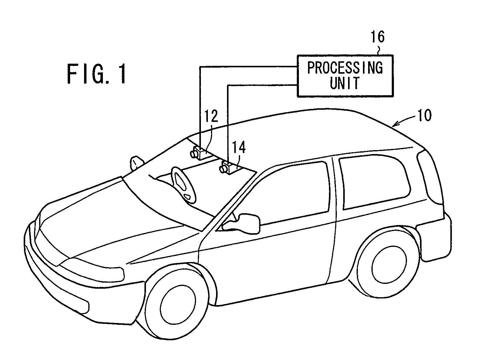
[0055]FIG. 1 shows a vehicle 10 (mobile object) according to an embodiment to which a plane detecting apparatus and a plane detecting method according to the present invention is applied. The vehicle 10 has a windshield on which there are fixedly mounted a base camera 12 and a reference camera 14 in upper left and right regions thereof as a pair of image capturing means for capturing images including a road plane area where the vehicle 10 travels. The base camera 12 and the reference camera 14 are stereo cameras comprising CCD cameras or the like with a common image capturing area set therein. The base camera 12 and the reference camera 14 are connected to a processing unit 16 for processing captured images to detect the road plane area and an object which may possibly become an obstacle. In the description which follows, an image captured by the base camera 12 will be referred to as a base image, and an image captured by the reference camera 14 as a reference image.
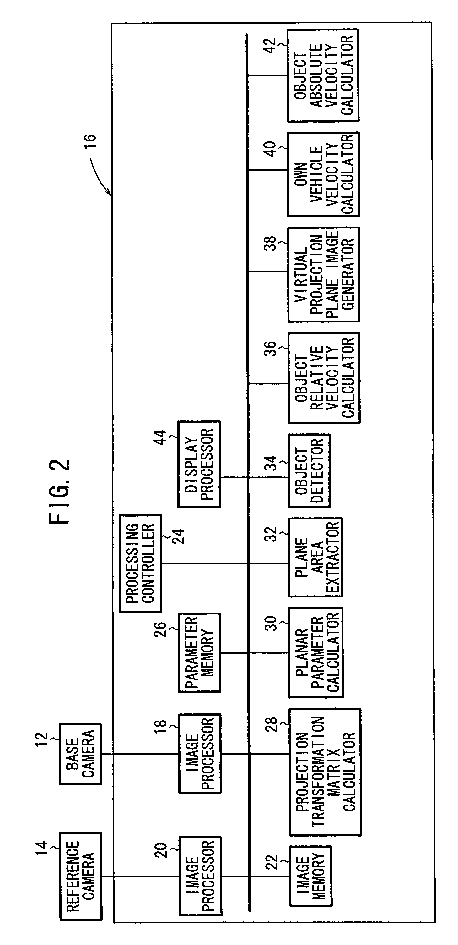
[0056]FIG. 2 is ...


PUM


Abstract

A rotation matrix and a translation vector between a basic camera and a reference camera are read out from a parameter storage section. At a projection conversion matrix calculating section, a projection conversion matrix capable of overlapping the road plane area included in images picked up by the basic camera and the reference camera is calculated by using the rotation matrix and the translation vector.

Description

TECHNICAL FIELD[0001]The present invention relates to a plane detecting apparatus and a plane detecting method for detecting a plane that can be traveled by a mobile object from an image captured by a pair of image capturing means mounted in the mobile object, in order to implement vehicle driver assistance and automatic cruise for an autonomous mobile vehicle, for example.BACKGROUND ART[0002]Processes for detecting a road plane area that can be traveled or detecting an obstacle that is present in a traveling environment in guiding a mobile object such as an autonomous mobile vehicle or the like are roughly classified into processes using a laser radar, ultrasonic waves, a milliwave radar, etc., and processes using images.[0003]The detecting processes using a laser radar and a milliwave radar are problematic in that the apparatus used are generally expensive and a sufficient spatial resolution cannot be achieved. The detecting processes using ultrasonic waves are problematic in that...

Claims


Application Information

Patent Timeline
Patent Type & Authority Patents(United States)
IPC IPC(8): G06K9/00G06K9/36
CPCG06T7/002G06T7/0026G06T7/0075G06K9/00805G08G1/161G06T2207/20224G06T2207/30261G06T2207/10021G06T7/85G06T7/32G06T7/593G06V20/58
Inventor FUJIMAKI, TOMOOKUTOMI, MASATOSHI
Owner HONDA MOTOR CO LTD
Why Eureka
Try Eureka