
Active coordinated tracking for multi-camera systems

a multi-camera system and active coordination technology, applied in the field of vision systems, can solve the problems of difficult to track one or more targets with fixed focal length cameras, difficult to track single ptz cameras, and master does not know how to command the slave camera next to track the target, etc., to achieve the effect of minimizing the cost matrix

Active Publication Date: 2012-05-15
SRI INTERNATIONAL
View PDF21 Cites 35 Cited by
  • Summary
  • Abstract
  • Description
  • Claims
  • Application Information

AI Technical Summary

Benefits of technology

The patent describes a method and system for coordinated tracking of objects using multiple images from different nodes. The method involves identifying the target object in each image, fusing the tracking information from each node to create a single fused track, and assigning one of the nodes to track the target object based on minimizing a cost function. The system includes image capturing devices such as PTZ cameras and sensors like GPS devices and radar-based devices. The method can also use the k-redundancy method to assign multiple sensors to a task and remove unassigned sensors from the pool. The technical effects of this patent include improved accuracy and efficiency in object tracking and better utilization of sensor resources.

Problems solved by technology

Tracking one or more targets with fixed focal length cameras is difficult to accomplish and produces approximate results at best.
Movable PTZ cameras have time-varying fields of view, which makes single PTZ camera tracking more challenging than for fixed cameras.
In the case of systems employing PTZ cameras having a single master and a plurality of slaves, if a target that is initially visible to a master becomes visible only to the slave camera and not to the master camera, the master does not know how next to command the slave camera to track the target.

Method used


Image

  • Active coordinated tracking for multi-camera systems
  • Active coordinated tracking for multi-camera systems
  • Active coordinated tracking for multi-camera systems

Examples


Embodiment Construction

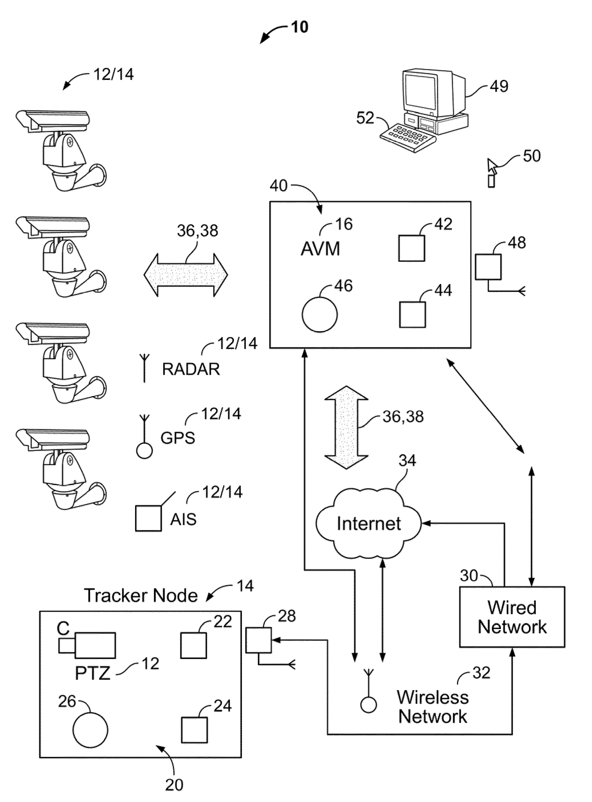
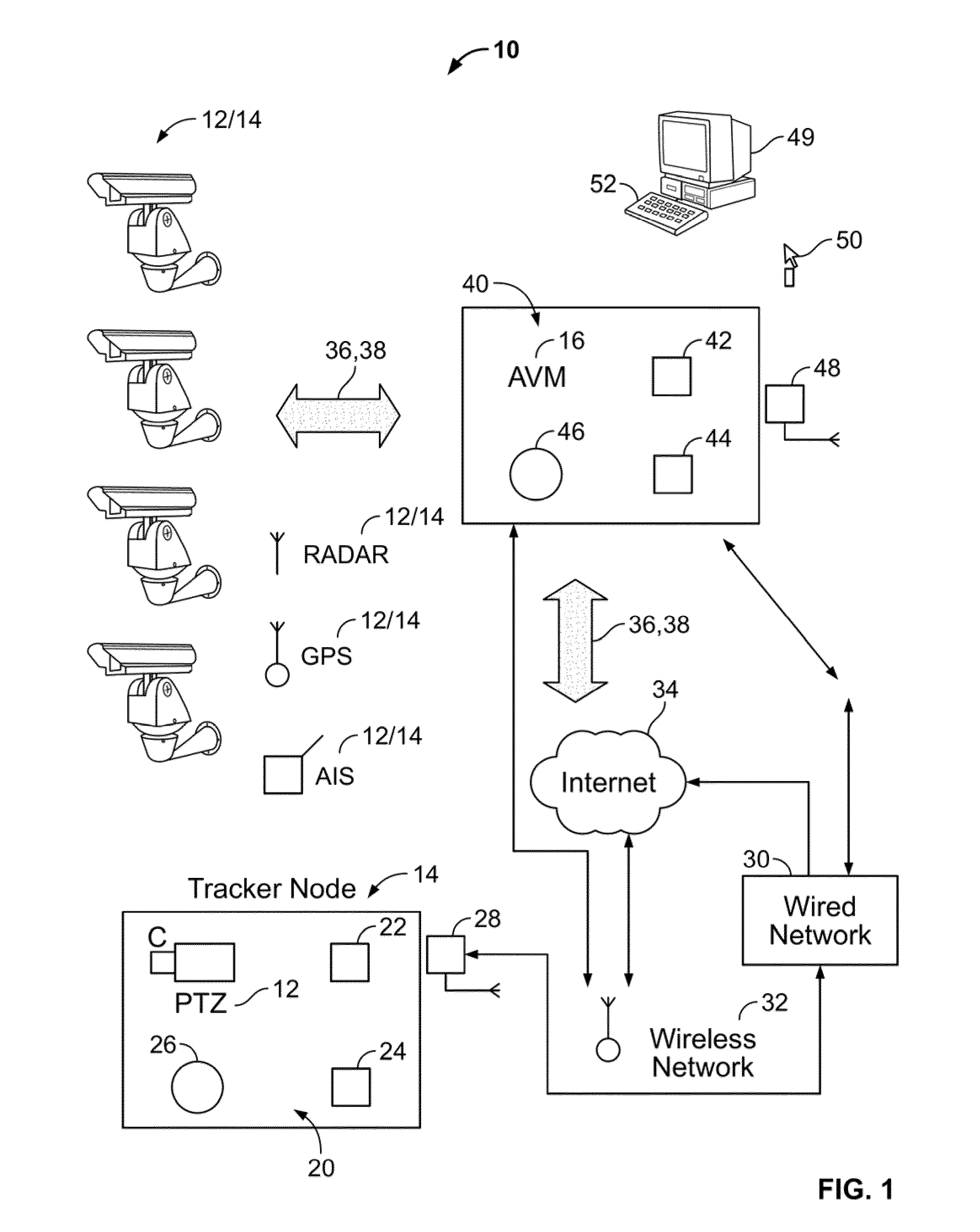
[0026]FIG. 1 illustrates an exemplary hardware architecture of an active collaborative tracking (ACT-vision) system 10 for coordinated tracking of objects, according to an embodiment of the present invention. The ACT-vision system 10 is configured to automatically control a plurality of individual PTZ cameras to follow a particular target, or a set of targets, to optimize arbitration among the PTZ cameras, and to optimize PTZ camera-to-PTZ camera handoff for determining which PTZ camera(s) is the best camera(s) for tracking and maintaining focus upon one or more targets. The goal of the present invention is to optimize sensor assignment to obtain the best quality coverage of one or more targets given the availability of one or more sensors.

[0027]According to an embodiment of the present invention, a strategy for tracking and maintaining targets in view assumes each camera is or can be modeled as a PTZ camera, i.e., a fixed camera may be thought of as a PTZ camera with a fixed locati...


PUM


Abstract

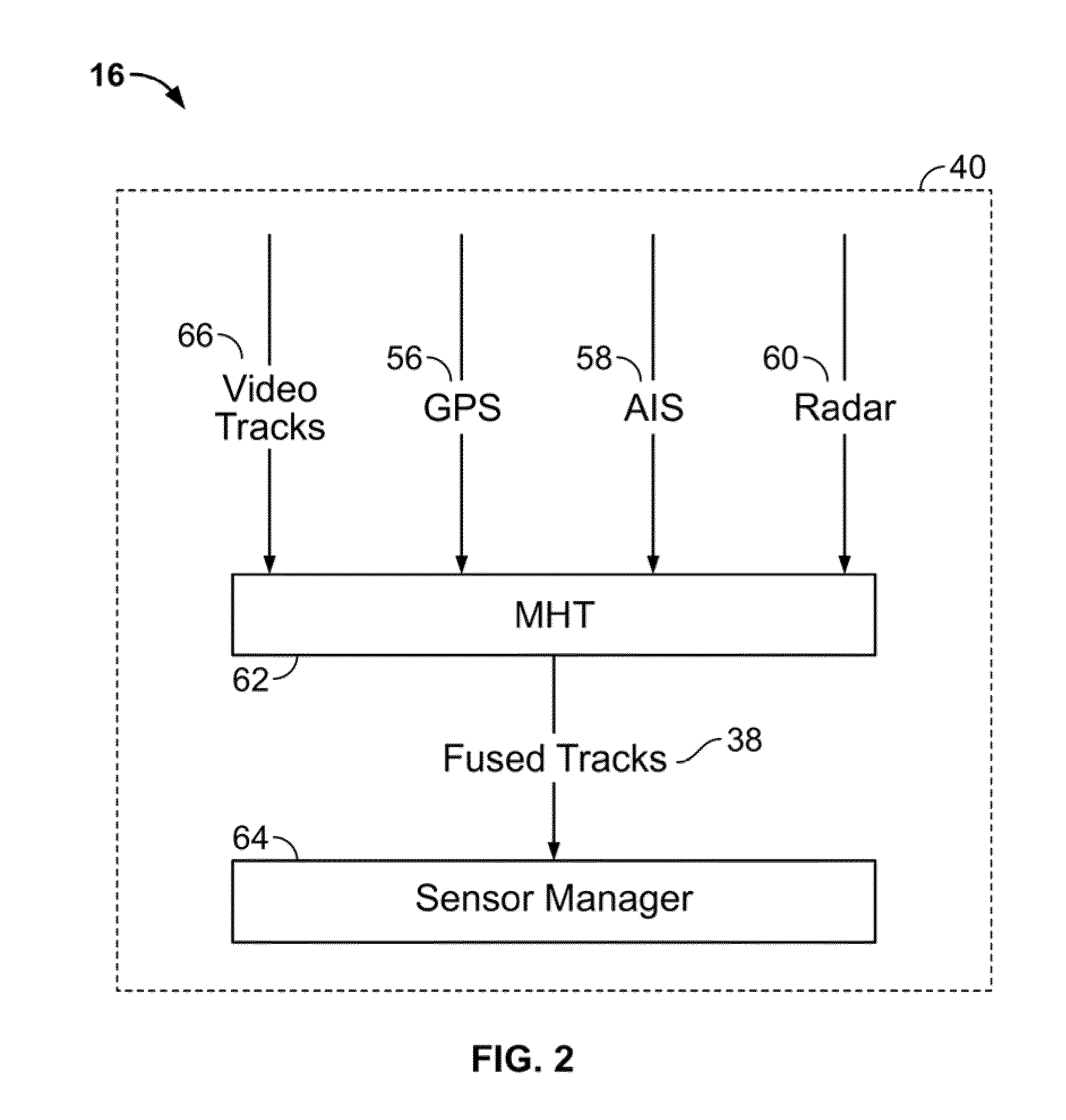
A method and system for coordinated tracking of objects is disclosed. A plurality of images is received from a plurality of nodes, each node comprising at least one image capturing device. At least one target in the plurality of images is identified to produce at least one local track corresponding to each of the plurality of nodes having the at least one target in its field of view. The at least one local track corresponding to each of the plurality of nodes is fused according to a multi-hypothesis tracking method to produce at least one fused track corresponding to the at least one target. At least one of the plurality of nodes is assigned to track the at least one target based on minimizing at least one cost function comprising a cost matrix using the k-best algorithm for tracking at least one target for each of the plurality of nodes. The at least one fused track is sent to the at least one of the plurality of nodes assigned to track the at least one target based on the at least one fused track.

Description

CROSS-REFERENCE TO RELATED APPLICATIONS[0001]This application claims the benefit of U.S. provisional patent application No. 61 / 152,374 filed Feb. 13, 2009, the disclosure of which is incorporated herein by reference in its entirety.FIELD OF THE INVENTION[0002]The invention relates generally to vision systems. More specifically, the invention relates to a system and method for automatically controlling a plurality of cameras to track one or more targets and to optimize arbitration and selection of the best available camera for tracking the one or more targets at any given time.BACKGROUND OF THE INVENTION[0003]There is considerable interest in large camera networks for automatic video analysis in surveillance, training and entertainment in both civilian and military. As the availability of sophisticated hardware increases, the engineering, military, and scientific communities may leverage the capabilities of large camera networks that cover several square kilometers in various applica...

Claims


Application Information

Patent Timeline
Patent Type & Authority Patents(United States)
IPC IPC(8): G06K9/00H04N7/18
CPCG01S3/7864G06T7/2093G08B13/19608G08B13/19645G08B13/19697G01S13/867G01S13/726G06T2207/20076G06T2207/20144G06T2207/30232G06T7/292G06T7/194
Inventor BROADDUS, CHRISTOPHER P.GERMANO, THOMASVANDERVALK, NICHOLASWU, SHUNGUANGDIVAKARAN, AJAYSAWHNEY, HARPREET SINGH
Owner SRI INTERNATIONAL
Learn More