
Power converter having a pivotable and receivable plug

a power converter and receivable technology, applied in the direction of coupling device connection, coupling protective earth/shielding arrangement, electrical equipment, etc., can solve the problems of complex structure requiring the use of many parts, not only complicated in manufacture, but also expensive in cost, and achieve the effect of reducing the number of parts and simplifying the structur

Active Publication Date: 2012-05-22
CYBER POWER SYST
View PDF26 Cites 32 Cited by
  • Summary
  • Abstract
  • Description
  • Claims
  • Application Information

AI Technical Summary

Benefits of technology

[0013]An objective of the present invention is to provide a pivotable and receivable power plug implemented with a simplified structure and minimum parts.
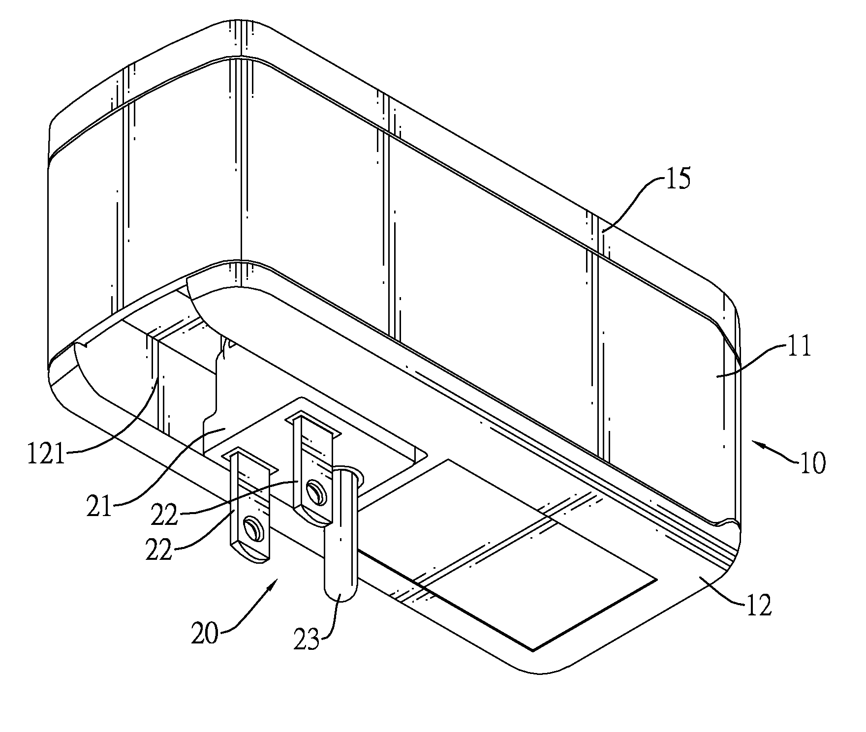
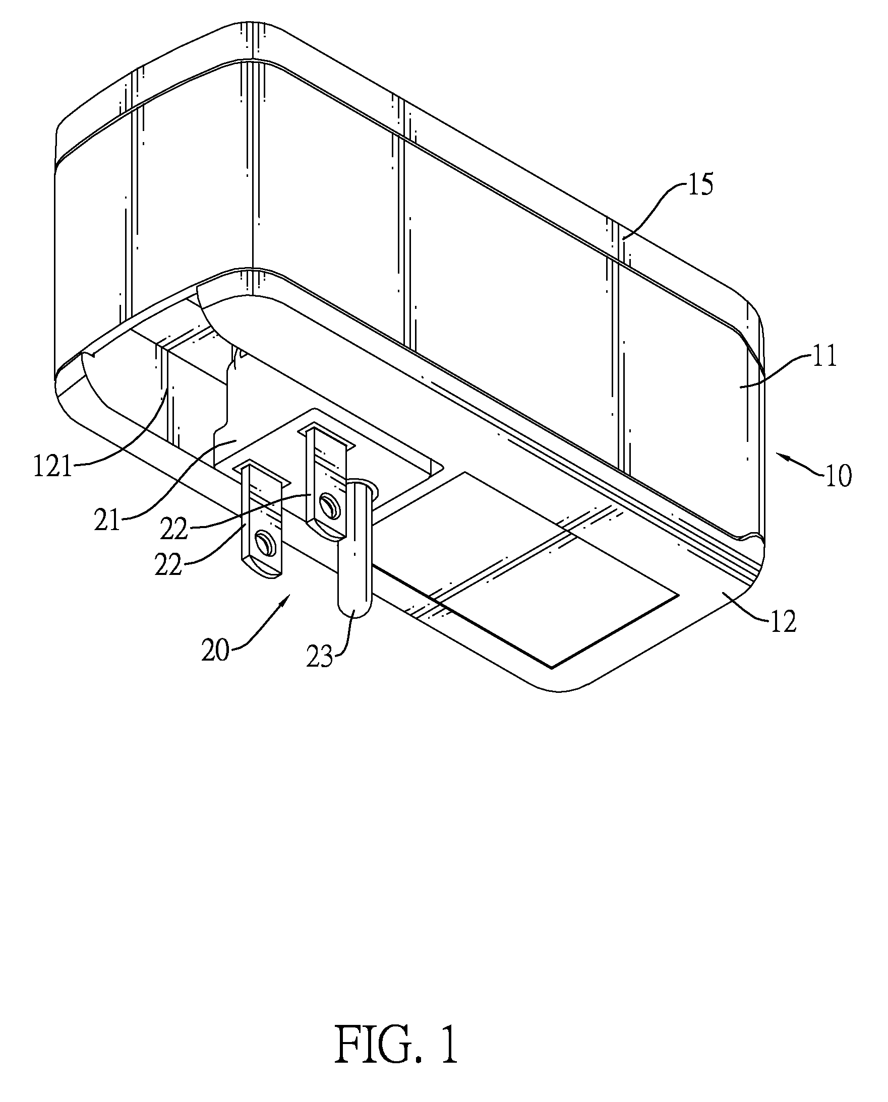
[0023]When the plug is pivoted and the prongs and the ground pin protrude beyond the rectangular opening of the housing, the second engagement portion of the ground plate engages the first engagement portion of the grounding strip to position the plug. The prongs and the ground pin are further plugged into a power socket, and power can be transmitted to the power output unit through the prongs, the metal pivot shafts, the shaft holders and the adapter board. When the plug is received, the first engagement portion can disengage from the second engagement portion by gently applying a force on the plug, and the plug can be pivoted to return to the housing, and the prongs and the ground pin of the plug are hidden inside the housing. Thus, a power conversion device having a pivotable and receivable plug can be achieved with a simple structure and minimum parts.

Problems solved by technology

Usually, the power plugs of the power conversion devices are stationary and are uneasy to be receivable for being bulky.
Such structure requiring the use of many parts is not only complicated in manufacture but also expensive in cost.

Method used


Image

  • Power converter having a pivotable and receivable plug
  • Power converter having a pivotable and receivable plug
  • Power converter having a pivotable and receivable plug

Examples


second embodiment

[0045]With reference to FIGS. 10 and 11, a power converter having a pivotable and receivable power plug in accordance with the present invention has a housing 10′, a power output unit 40′ and a plug 20.

[0046]The housing 10′ has a body 11′, a bottom cover 12′, two conducting strips 32 and a grounding strip 33. The body 11′ has a chamber 13, an open side, a cable hole 16 and two pivot shaft slots 14. The chamber 13 is defined in the body 11′. The open side is formed through a bottom of the body 11′. The cable hole 16 is formed through a rear wall of the body 11′. The pivot shaft slots 14 are respectively formed on two lateral inner walls of the body 11′. The bottom cover 12′ covers the open side of the body 11′ and has a rectangular opening 121 formed through the bottom cover 12′. Each conducting strip 32 is resilient and has a shaft holder 321 formed by bending a free end of the conducting strip 32, being U-shaped and securely mounted in one of the pivot shaft slots 14 by abutting ag...

first embodiment

[0049]In contrast to the first embodiment, the power output unit of the present embodiment has multiple power wires directly connected with the corresponding conducting strips 32 and the grounding strip 33 to constitute a power cable having a pivotable plug.

[0050]In sum, the present invention requires no additional pivot shafts and pivot shaft holders because the metal pivot shaft 25 of the plug 20 and the shaft holders 321 are directly formed by respectively bending the free ends of the conducting strips 32. Additionally, the engagement mechanism directly formed on the conducting strip 33 and the ground plate 24 of the plug 20 positions the plug when the plug 20 is pivoted and thus requires no additional positioning parts. Accordingly, the present invention can be manufactured with minimum parts and is cost-saving.


PUM


Abstract

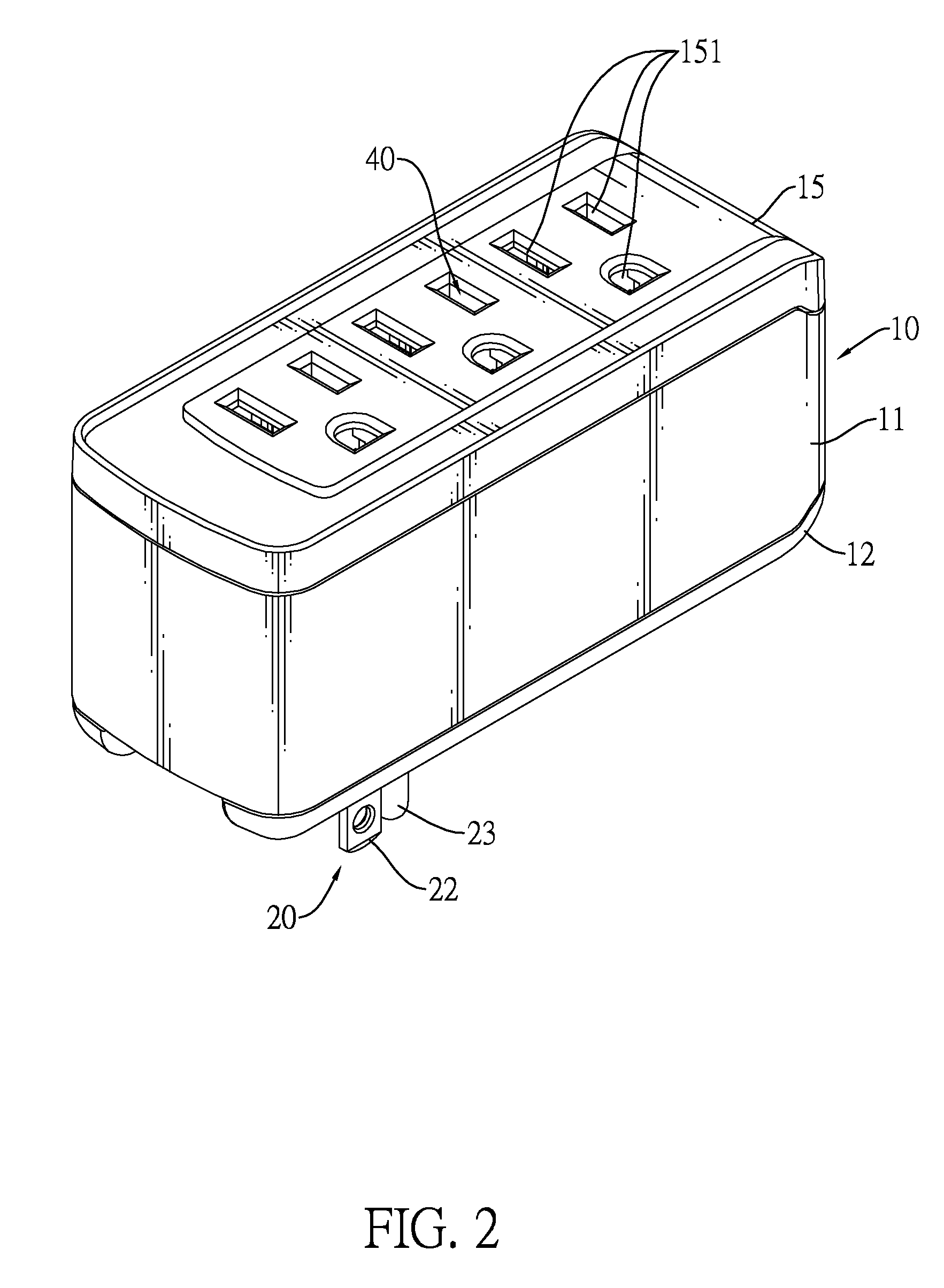
A power converter having a pivotable and receivable power plug has a housing, an adapter board, a power output unit and a plug. The adapter board and the power output unit are mounted inside the housing. The adapter board has two conducting strips and a grounding strip. Each conducting strip has a shaft holder formed by bending a free end of the conducting strip, and two metal pivot shafts formed on two opposite sides of the plug are pivotally and respectively mounted in the shaft holders. The plug has a ground plate having a first engagement portion formed thereon. The grounding strip has a second engagement portion formed therein in a pivoting path of the plug to engage the first engagement portion and position the plug when the plug is pivoted and protrudes beyond the housing. Accordingly, the power converter can have a pivotable and receivable plug with minimum parts.

Description

BACKGROUND OF THE INVENTION[0001]1. Field of the Invention[0002]The present invention relates to a power plug, and more particularly to a pivotable and receivable power plug implemented with a simplified structure and minimum parts.[0003]2. Description of the Related Art[0004]An industrial society heavily and increasingly relies on the use of electric appliances. For the sake of diversified electric appliances in the market and power conversion devices specifically equipped for the electric appliances, a wide range of power conversion devices, such as power extension cords, transformers and rectifiers, are brought into play in that regard. As the power conversion devices must be connected with power sockets of power sources, each power conversion device needs to have a power plug to plug in a corresponding power socket. Usually, the power plugs of the power conversion devices are stationary and are uneasy to be receivable for being bulky.[0005]With reference to FIG. 12, a convention...

Claims


Application Information

Patent Timeline
Patent Type & Authority Patents(United States)
IPC IPC(8): H01R13/44
CPCH01R13/652H01R13/6675H01R25/003H01R31/065H01R35/04
Inventor CHENG, HSIUNG-KUEITSENG, CHUNG-CHIENKAO, MING-TSAI
Owner CYBER POWER SYST
Learn More